
TM 5-3805-298-23-2
0155
Table 1. Kickout System Will Not Operate or Operates Improperly Continued.
0155
MALFUNCTION
TEST OR INSPECTION
CORRECTIVE ACTION
c. Slide shaft out of channel so
Kickout System Will Not
that shaft magnet passes over
Operate or Operates
bucket kickout position sensor.
Improperly - Continued
Yellow LED will turn ON. When
LED is illuminated, multimeter
should display voltage of 18 to
26 V.
d. Set bucket/fork switch to fork
position (TM 5-3805-298-10).
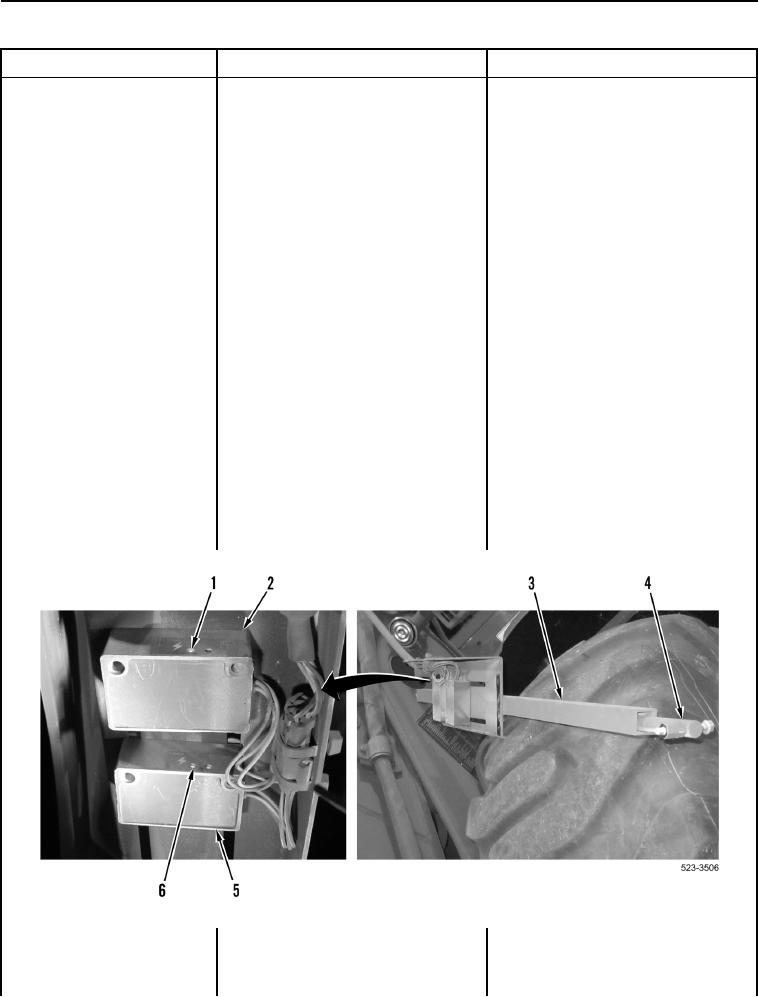
e. Slide shaft into channel so that
shaft magnet passes over fork
kickout position sensor
(Figure 12, Item 2). Yellow LED
(Figure 12, Item 1) will turn
OFF. When yellow LED is OFF,
multimeter should display 0L.
f. Slide shaft out of channel so
that shaft magnet passes over
fork kickout position sensor.
Yellow LED will turn ON. When
LED is illuminated, multimeter
should display voltage of 18 to
26 V.
g. Repeat steps a through f to
verify operation as necessary.
Figure 12. Testing Fork and Bucket Kickout Signal Circuits to Pilot Valve.
0155

