
TM 5-3805-298-23-4
0375
INSTALLATION
000375
NOTE
Install and route hydraulic hosed as noted during removal.
Install wiring harness connectors and route wiring harness as noted during removal.
Install elbow fittings as noted during removal.
1. Install three new O-rings (Figure 3, Item 7), elbow fittings (Figure 3, Item 5), and jam nuts (Figure 3, Item 6) on
hydraulic lock-out valve (Figure 3, Item 2).
2. Install four new O-rings (Figure 3, Item 8), hydraulic lock-out solenoid (Figure 3, Item 9), and two bolts
(Figure 3, Item 11) on hydraulic lock-out valve (Figure 3, Item 2).
3. Install three new O-rings (Figure 3, Item 4), hoses (Figure 3, Item 1), and tube nuts (Figure 3, Item 3) on elbow
fittings (Figure 3, Item 5).
4. Install hydraulic lock-out valve (Figure 3, Item 2), two washers (Figure 3, Item 15), bolts (Figure 3, Item 14),
washers (Figure 3, Item 12), and nuts (Figure 3, Item 13) on machine.
5. Connect lower cab wiring harness connector (Figure 3, Item 10) on hydraulic lock-out solenoid (Figure 3,
Item 9).
NOTE
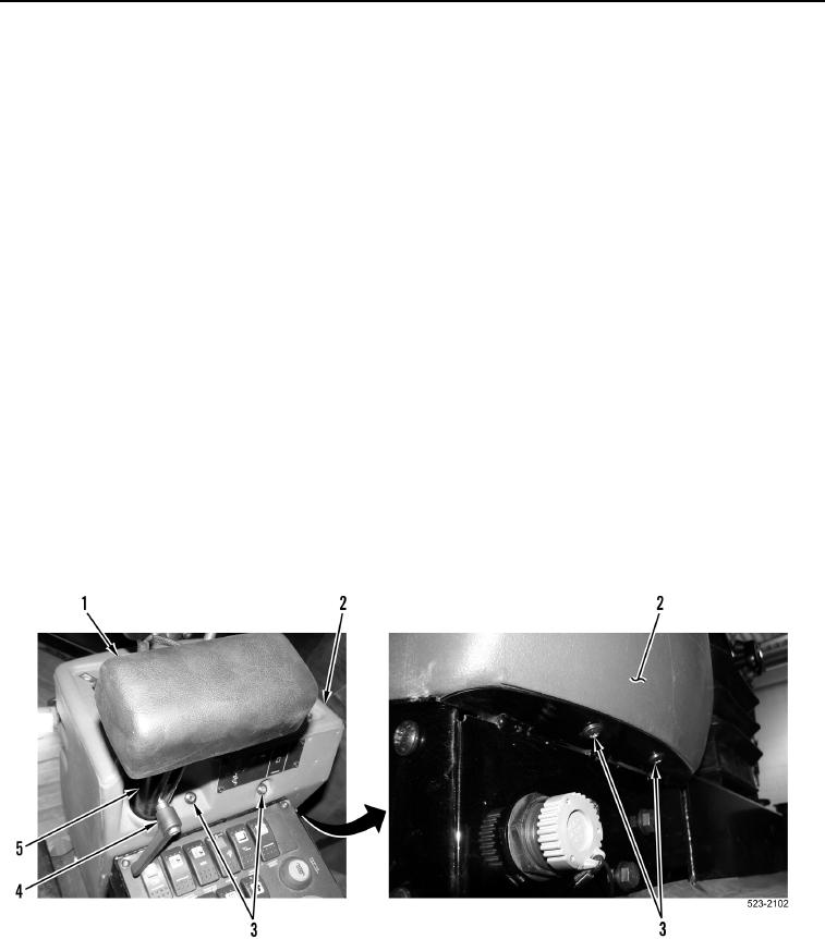
Two bolts are located at top rear and two bolts are located at bottom front of operator
console.
6. Install operator console cover (Figure 4, item 2) and four bolts (Figure 4, Item 3) on machine.
7. Install arm rest (Figure 4, Item 1) and control lever (Figure 4, Item 4) on support post (Figure 4, Item 5).
Figure 4. Arm Rest and Operator Console Cover.
0375

