
TM 5-2420-231-23-1
0061
Table 1. 4-Wheel Drive (4WD) Does Not Engage - Continued.
061
MALFUNCTION
TEST OR INSPECTION
CORRECTIVE ACTION
4. Using a digital multimeter, mea-
4-Wheel Drive (4WD) Does
Resistance 5.0 Ohms or Less -
sure resistance between power-
Replace transmission (WP 0213).
Not Engage - Continued
shift connector wiring harness
Proceed to Test Step 22.
connector (WP 0007, Figure 20)
Resistance Greater Than 5.0 Ohms -
terminal B1 and powershift wiring
Replace powershift wiring harness
harness connector (WP 0007, Fig-
(WP 0167).
ure 146) terminal H. Resistance
Install front floor cover plate (WP 0306).
should be 5.0 ohms or less.
Proceed to Test Step 22.
Test Step 18. Test Brake Pressure
Switch Voltage Supply Circuit.
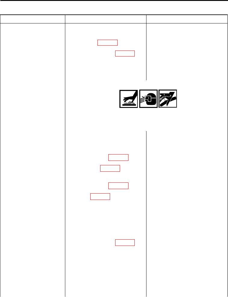
WARNING
Allow hydraulic system to cool before performing procedure. Hot
hydraulic fluid can cause severe burns. Wear eye, hand, and skin
protection when working with heated parts. Failure to follow this warning
may result in injury to personnel.
1. Turn ignition switch to the off posi-
tion (TM 5-2420-231-10) and dis-
connect batteries (WP 0157).
2. Disconnect powershift wiring har-
ness connector (WP 0007, Figure
200) from right-hand brake pres-
sure switch (WP 0007, Figure 201)
(WP 0169).
3. Disconnect powershift wiring har-
ness connector (WP 0007, Figure
202) from left-hand brake pressure
switch (WP 0007, Figure 203) (WP
0169).
4. Have an assistant connect batter-
ies (WP 0157) and turn ignition
switch to the on position (TM 5-
2420-231-10).
5. Using digital multimeter, measure
Voltage 8.5 to 10 Volts - Proceed to
voltage between powershift wiring
step 6.
harness connector (WP 0007, Fig-
Voltage Less Than 8.5 Volts - Proceed
ure 202) terminal A and machine
to Test Step 19.
ground. Voltage should be 8.5 to
10 volts.
0061-15