
TM 5-3805-255-14
0004
GENERAL
0004
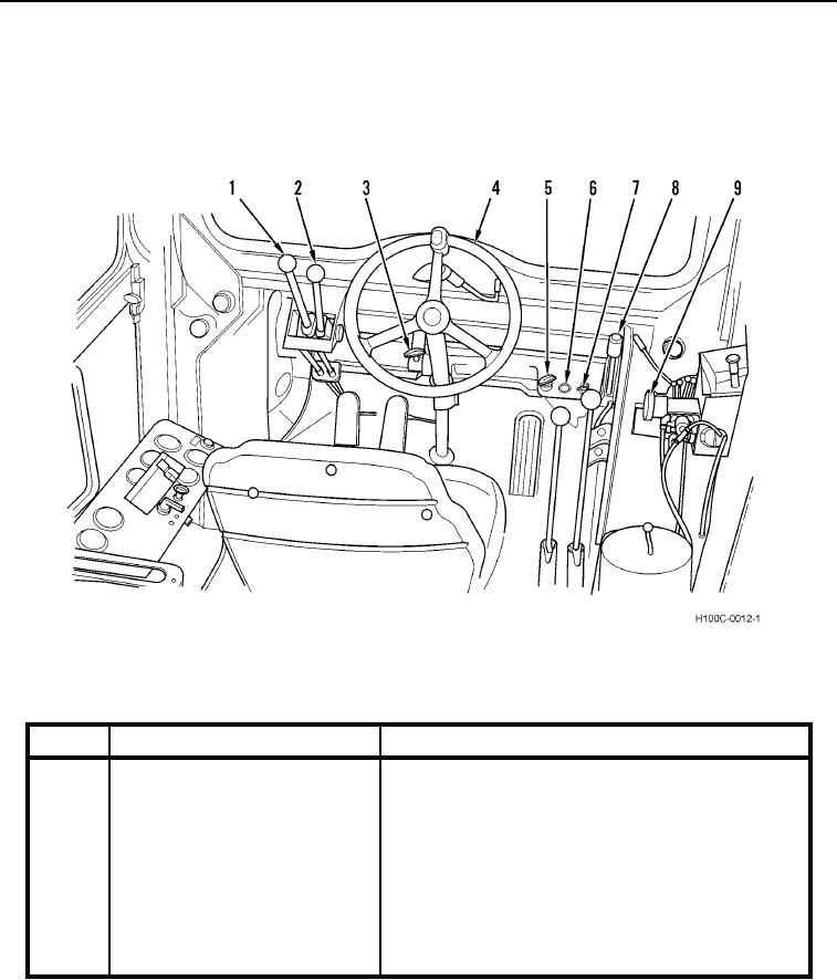
This work package describes, locates, and illustrates the controls and indicators used on the H100C Loader.
Become familiar with the location and function of all operator controls and indicators described in this work
package before operating or performing operator maintenance on the loader.
OPERATOR CONTROLS
0004
Figure 1. Controls.
04
KEY
COMPONENT OR INDICATOR
DESCRIPTION
04
04
04
1
Transmission Gear Select Range
This lever is used to select any one of the transmission
Lever
gear ranges.
2
Transmission Direction Lever
This lever is used to select loader direction.
3
Engine Shutdown Control
The engine shutdown control is located to the left of the
steering column on the underside of the instrument
panel box. Pull the control handle out all the way to shut
the engine down. After the engine has stopped
completely, push the handle back in. The shutdown
control stops the fuel supply to the engine.
0004-2