
TM 5-3805-255-14
0005
SAFETY BAR AND PINS CONTINUED
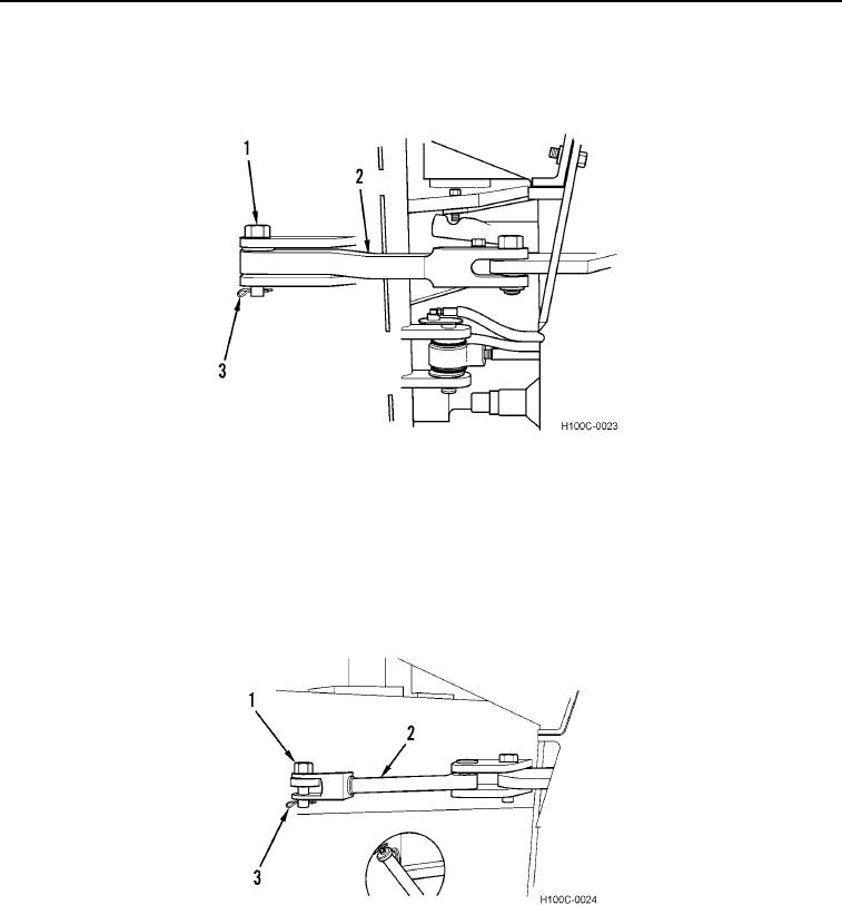
1. To lock the loader halves in straight position, the bar (Figure 2, Item 2), two pins (Figure 2, Item 1), and a cotter
pin (Figure 2, Item 3) are used as shown in Figure 2.
Figure 2. Safety Bar in Straight Lock Position.
0005
2. To lock the loader in a full turn, only one pin (Figure 3, Item 1) is used. Turn the loader to its full turn position
and insert the pin through the holes on the closed side of the loader as shown in Figure 3. Lock pin in place
with cotter pin (Figure 3, Item 3). Always check that the bar (Figure 3, Item 2) and pins have been replaced in
storage position on the left side of the loader before operating. Broken or lost safety bar and pins should be
repaired or replaced immediately to ensure that the safety device is always available for use. Do not attempt to
service or transport the loader if the safety bar or pins are broken or missing.
Figure 3. Safety Pin Installed in Full Turn Lock Position.
0005
0005-3