
TM 5-3805-255-14
0039
CLEANING AND INSPECTION CONTINUED
00039
5. Check by-pass valve spring for proper length, action, and condition. A spring outside of these standards must
be replaced.
a. Free length - 2.068 in. (52.53 mm).
b. Test length - 1.224 in. (31.09 mm).
c.
Test load - 6.92 lb (31 N.)
6. Check by-pass valve.
a. Outside diameter - 0.622 in. (15.80 to 15.82 mm).
b. Valve bore - 0.624 to 0.625 in. (15.85 to 15.88 mm).
c.
Running clearance - 0.001 to 0.003 in. (0.0254 to 0.0752 mm).
7. Check valve condition. Valves should slide freely, and valve seats in housing and filter head should not be worn
or damaged. Replace if damaged.
8. Check seal rings on oil outlet and inlet pipes for damage. Replace if damaged.
END OF TASK
INSTALLATION
00039
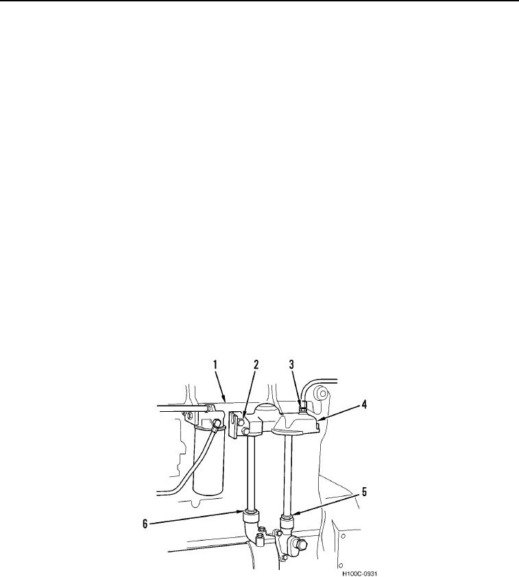
1. Install filter head (Figure 4, Item 4) and three capscrews (Figure 4, Item 2) on cylinder head (Figure 4, Item 1).
2. Connect turbocharger oil supply line (Figure 4, Item 3) to filter head (Figure 4, Item 4).
3. Install oil outlet pipe (Figure 4, Item 5) and oil inlet pipe (Figure 4, Item 6) and tighten nuts on each end of
pipes.
Figure 4. Oil Filter Head.
0039
0039-4