
TM 5-3805-255-14
0110
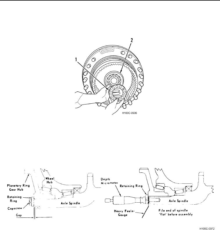
ASSEMBLY CONTINUED
11. Position retainer (Figure 11, Item 1) against ring gear hub (Figure 11, Item 2) WITHOUT shims. Secure retainer
with three equally spaced capscrews. Tighten capscrews evenly to 40 lb-ft (54 Nm) torque while rotating wheel
hub.
Figure 11. Retainer Installation.
0110
12. Carefully measure gap (Figure 12). Using a depth micrometer, measure through a bolt hole in retaining ring to
a heavy feeler gauge held across a threaded bolt hole in spindle. Add thickness of feeler gauge to micrometer
reading and subtract measured thickness of retaining ring to determine gap.
13. Measure shims individually to obtain a shim pack thickness equal to measured gap. To this shim pack add
additional 0.005 in. (0.127 mm) shim.
Figure 12. Shim Pack Determination.
0110
0110-10