TM 5-3805-255-14
0114
DISASSEMBLY CONTINUED
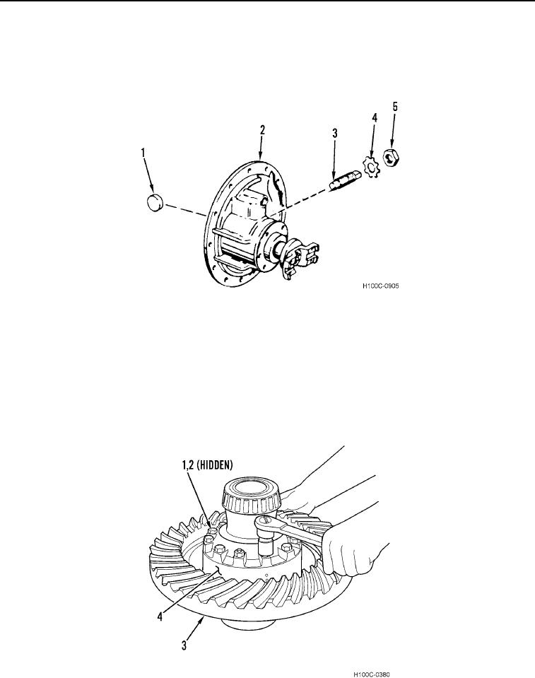
13. Remove nut (Figure 6, Item 5) and lockwasher (Figure 6, Item 4) from adjusting screw (Figure 6, Item 3). Dis-
card lockwasher.
14. Remove thrust block (Figure 6, Item 1) from carrier housing (Figure 6, Item 2).
15. Remove adjusting screw (Figure 6, Item 3) from carrier housing (Figure 6, Item 2).
Figure 6. Thrust Block Removal.
0114
16. Mark differential case halves (Figure 7, Items 3 and 4) to ensure correct alignment during assembly.
17. Remove lockwires (Figure 7, Item 2).
CAUTION
When removing plain half, do not allow side gear to drop. Failure to follow these
instructions may result in damage to components.
18. Remove 12 bolts (Figure 7, Item 1) from differential case halves (Figure 7, Items 3 and 4).
19. Lift plain half (Figure 7, Item 3) from flanged half (Figure 7, Item 4).
Figure 7. Differential Case Halves Separation.
0114
0114-6

