
TM 5-3805-255-14
0128
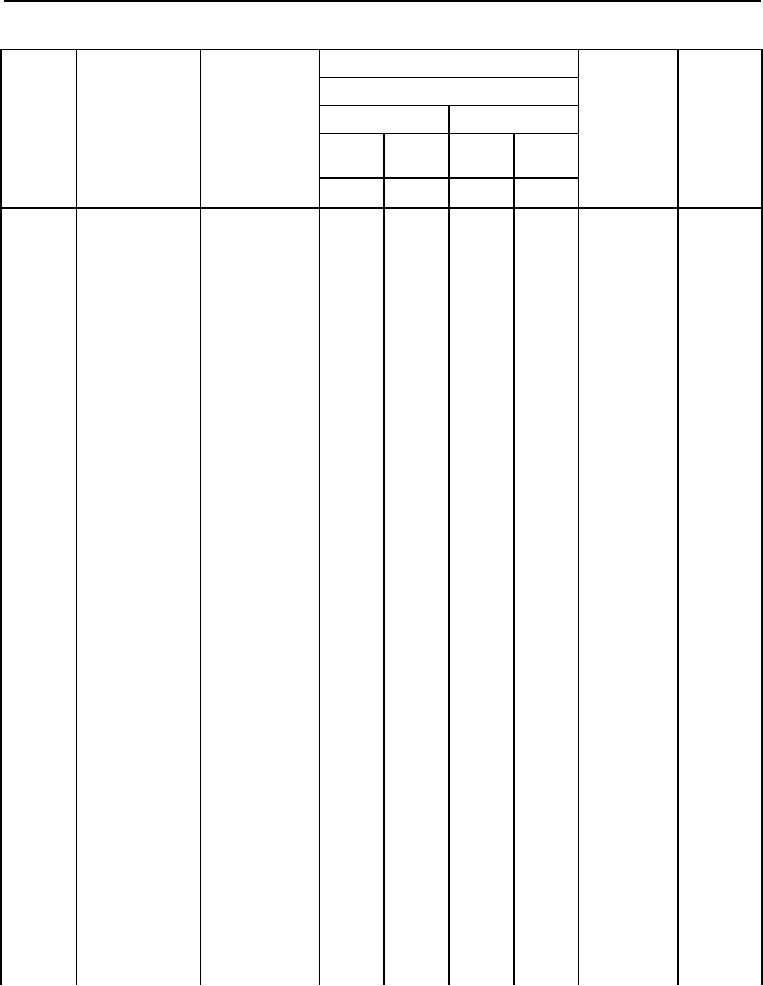
Table 1. Maintenance Allocation Chart for the H100C - (Continued).
(1)
(2)
(3)
(4)
(5)
(6)
MAINTENANCE LEVEL
FIELD
SUSTAINMENT
TOOLS AND
MAINT-
BELOW
EQUIPMENT
CREW
AINER
DEPOT
DEPOT
GROUP
COMPONENT/
MAINTENANCE
REFERENCE
REMARKS
C
F
H
D
NUMBER
ASSEMBLY
FUNCTION
CODE
CODE
BRAKES -
12
CONTINUED
1204
Hydraulic Brake
System
Spider
Inspect
1.0
Assembly
Replace
8.0
Repair
4.0
Power Cluster
Inspect
0.1
Assemblies
Replace
0.5
20
Repair
1.0
1208
Air Brake System
Treadle Valves, Service
0.1
Left and Right Replace
0.5
20
Repair
0.5
Hose and Tube Service
0.1
Assemblies
Replace
0.3
Repair
0.5
Reservoirs
Service
0.1
Replace
0.3
20
Relay Valve
Replace
1.5
Repair
1.5
Alcohol Injector Replace
0.6
Repair
1.0
20
Valves, Drain,
Replace
1.0
Safety, and
Repair
1.5
Check
1209
Air Compressor
Service
1.3
Assembly
Replace
2.0
14,20
Repair
4.0
Overhaul
6.0
Hose
Replace
1.0
Assemblies
Air Discharge
Replace
2.0
System Valve,
Discharge
Governor
Replace
0.5
Repair
1.0
0128-11