Engine Tune-Up
ENGINES WITH FOUR VALVE CYLINDER HEADS
screw from turning with a screw driver and tighten the
The exhaust valve bridges must be adjusted and the
lock nut on the adjustment screw. Complete the
adjustment screws locked securely at the time the
operation by tightening the lock nut with a torque
cylinder head is installed on the engine. Until wear
wrench to 25 lb-ft (34 Nm), being sure that the screw
occurs. no further adjustment is required on the
does not turn.
exhaust valve bridges. When wear is evident. make the
necessary adjustments as outlined below.
7. Lubricate the bridge guide and the bridge pilot with
engine oil.
Exhaust Valve Bridge Adjustment
8. Reinstall the bridge in its original position.
1. Remove the loose dirt from the valve rocker covers
and remove the covers. Remove the injector fuel pipes
9. Place a .0015" feeler gage under each end of the
and' the rocker arm bracket bolts. Move the rocker
bridge. When pressing down on the pallet surface of
arms away from the exhaust valve bridge.
the bridge, both feeler gages must be tight. If both
feeler gages are not tight, readjust the screw as
2. Remove the exhaust valve bridge (Fig. 2).
outlined in Steps 5 and 6.
3. Place the bridge in a vise or holding fixture J 21772
10. Adjust the remaining bridges as outlined above.
and loosen the lock nut on the bridge adjusting screw.
11. Swing the rocker arm assembly into position being
CAUTION: Loosening or tightening the lock nut
sure the bridges are properly positioned on the rear
with the bridge in place may result in bending
valve stems. This precaution is necessary to prevent
the bridge guide or the rear valve stem.
valve damage due 10 mislocated bridges.
4. Install the bridge on the bridge guide.
12. Tighten the rocker arm bracket bolts to 90-100 lb-
ft (122-136 Nm) torque.
5. While firmly pressing straight down on the pallet
s u r f a c e of the bridge, turn the adjusting screw
13. Align the fuel pipes and connect them to the
clockwise until it Just touches the valve stem. Then turn
injectors and the fuel connectors. Use socket J 8932 to
the screw an additional 1/8 to 1/4 turn clockwise and
tighten the connectors t o 12-15 lb-ft (16-20 Nm)
tighten the lock nut finger tight.
torque.
6. Remove the bridge and place it in a vise. Hold the
CAUTION: Do not bend the fuel pipes and do
not exceed the specified torque. Excessive
tightening will twist or fracture the flared ends
of the fuel pipes and r e s u l t i n l e a k s .
Lubricating oil diluted by fuel oil can cause
serious damage to the engine bearings.
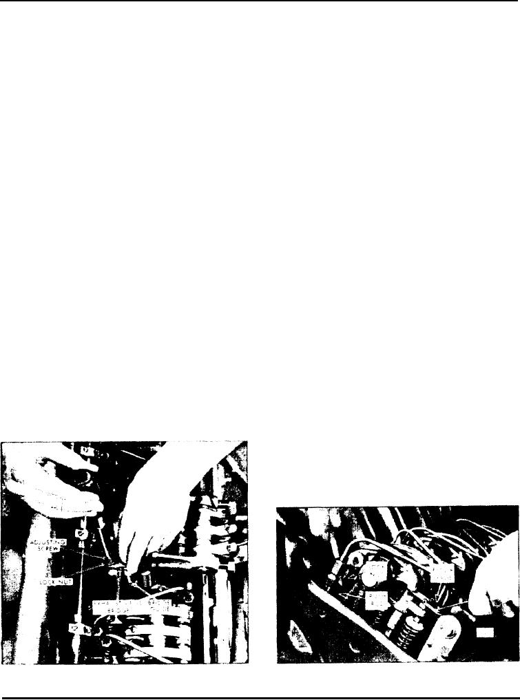
Fig. 3 - Adjusting Valve Clearance
Fig. 2 - Bridge Balancing Adjustment
Page 89

