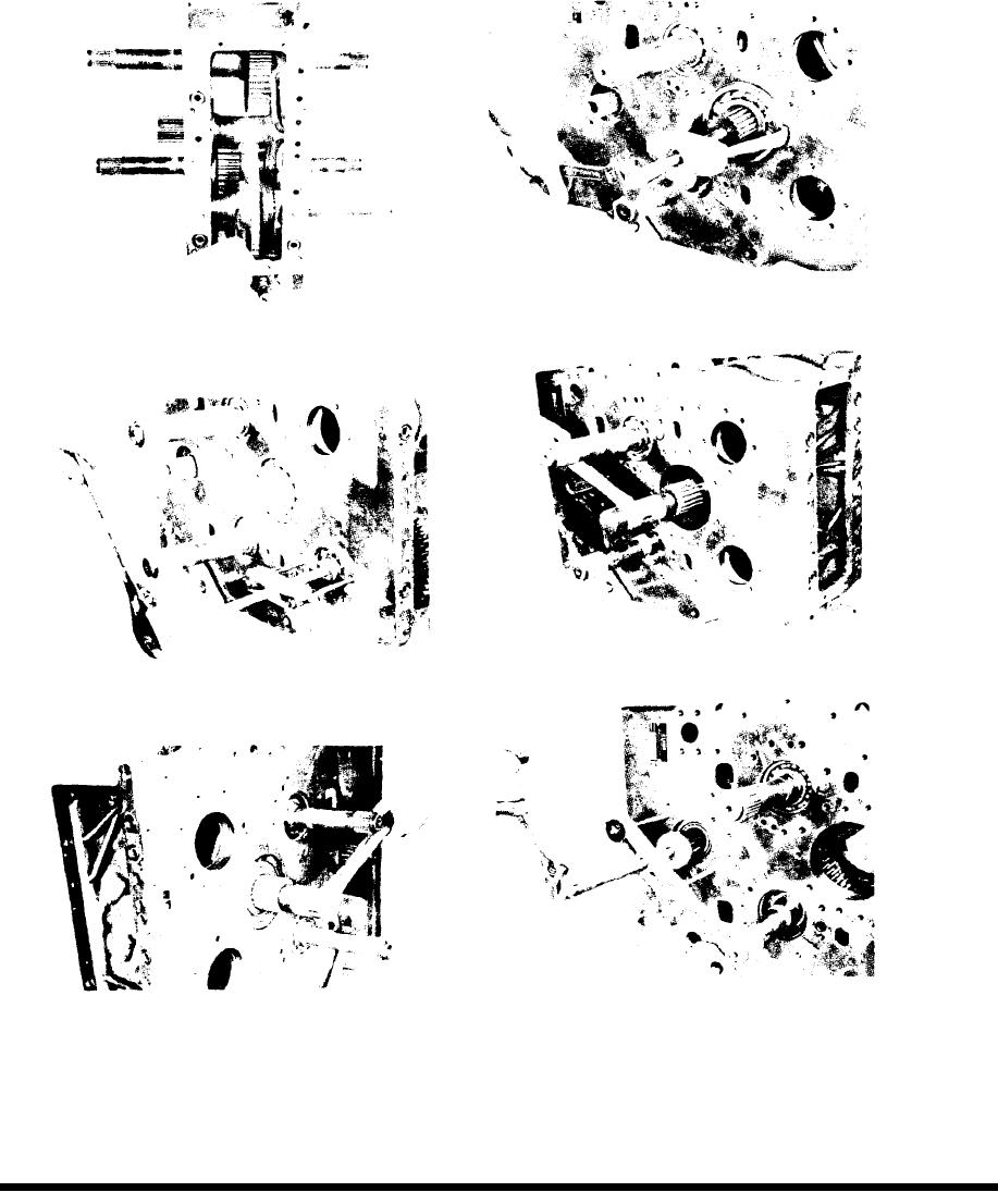
Figure 42
Using a suitable bearing puller, remove bearing from
shaft.
Figure 39
Remove reverse gear retainer ring from ring groove.
Figure 43
Top idler shaft and bearing from case.
Figure 40
Using a suitable shaft pusher tool, remove reverse
shaft and gear from case.
Figure 44
Figure 41
Block output shaft gears and using a suitable shaft
Tap idler shaft and bearing through case until bear-
pusher tool, remove output shaft and gears from case.
ing on opposite side is out at least one half an inch.
-24-

