
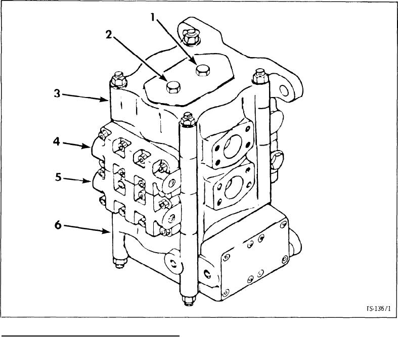
Valve Assembly, Main
No.
Part No.
Description
Qty.
2
A
2504922
1
Control valve assy
B
✝ 961198
1
Repair kit minor
C
✝ 961199
Repair kit major
1
1
948847
1
Plug
1 A ✝ 91F-3
1
O-ring
2
948847
1
Plug
2A ✝ 91F-3
1
O-ring
3----
3
1
Cover section
4
4
961206
1
Boom section
5
961203
5
1
Bucket section
6
6
961202
1
Control section
✝ 7948854
7
1
Relief valve assy
2
Inc 1 7 Where replacing any section of Valve Minor Repair Kit 961198 must also or used
For purpose of identification, illustration above indicates by numberical designation the individual section group location in control valve. Code to
numerical designation also appears in heading of each section covered in parts listing heroin
3
See A
4
See page V8
5
See page V9
6
See page Vl0
7
See page V11
V7-2