
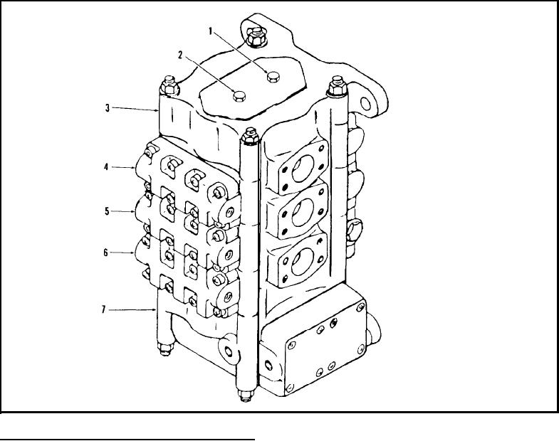
Valve Assembly - Main (Three Spool)
TS-14290
Part No.
No.
Description
Qty.
2
A
2504921
1
Control valve assy
B
†961200
1
Repair kit minor
1
†961201
C
Repair kit major
1
948847
1
Plug
†91F-3
1
1A
O-ring
2
948847
1
Plug
2A
†91F-3
1
O-ring
3----
3
1
Cover section
4
4
961205
1
Optional section
5
Boom section
5
961206
1
6
6
961203
1
Bucket section
7.8
7
961202
1
Control section
†9948854
Relief valve assy
8
1
2
Inc. 1 ➜ 8 When replacing any section of Valve, Minor Repair Kit 961200 must also be used.
For purpose of identification, illustration above indicates by numerical designation the individual section group location in control valve. Code to
numerical designation also appears in heading of each section covered in parts listing herein.
4
See A
4
See page Z18
5
See page Z19
6
See page Z20
7
See page Z21
8
Inc. 8
9
See page Z23
Z17-2