TM 5-3805-258-24-1
9506 STEERING SYSTEM
SPECIFICATl~s
ARTICULATED HITCH GROUP
Models 950BS and 950BNS
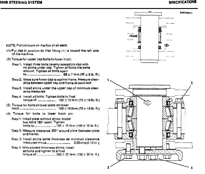
NOTE: Put lubricant on the lips of all seals,
(1) Put cap in position 30 that fitting (1) is toward the left side
of the machine.
(2) Torque for upper cap bolts in lower hitch:
Step 1:
Step 2:
Step 3:
Step 4:
(3) Toraue
Install three bolts (evenly spaced) in cap with
no shims under cap. Tighten all bolts the same
amount. Tighten all bolts again
to . . . . . . . . . . . . . . . . . . . . . . .
88 t 7 Nom (65 f 5 lb, ft.)
Make sure lower cap is against frame. Measure clear-
ance between upper cap and frame at each bolt.
Install shims under the upper cap of minimum clear-
ance measured.
Install all bolts. Tighten bolts to final
torque of
. . . . . . . . . . . . .
100 f 15 N.m (75 t 10 lb. ft.)
for bolts in lower Dlate on lower
hitch . . . . . . . . . . . . . . . . . . . . . . . . .
100 x 15 N.m (75 t 10 lb. ft.)
(4)
Torque
for
bolts
in
lower
hitch
pin:
Step 1: Install plate without shims, Install
two bolts 160” apart. Tighten
bolts to . . . . . . . . . . . . . . 135 f15N.m(100 tlOib, ft.)
Step 2: Measure clearance 360’ around plate (between plate
and frame),
Step 3: Install shims same thickness as minimum clearance
measured minus . . . . . . . . . . . . . . . .
0.25 mm (0.10 in. )
Step 4: With correct thickness shims, install
all bolts and tighten to a final
torque of . . . . . . . . . . . . 200 f25N.m(150 t201b. ft.)
2-54.1/2-54.2 (blank)


