
TM 5-3805-291-23-2
STEERING COLUMN REPLACEMENT - CONTINUED
0121 00
INSTALLATION - CONTINUED
17.
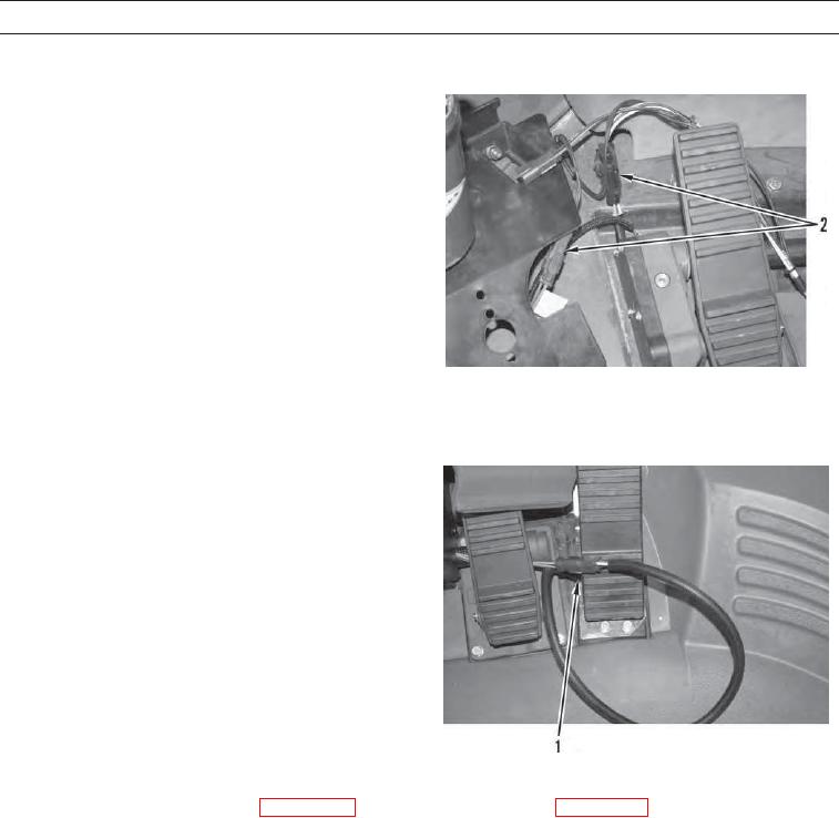
Connect two wiring harnesses (2) located on left side
of cab and install floor mat.
427-C1147
18.
Connect wiring harness (1) located on right side of cab
and install floor mat.
427-C1146
19.
If removed, install turnlamp lever (WP 0066 00) and transmission shift lever (WP 0101 00).
WAR N I N G
Before operating the machine, secure the steering frame lock in the stowed position. DO NOT operate
machine with steering frame lock connected. Steering frame lock must be disconnected and securely
stowed. Failure to follow this warning may result in injury or death to personnel.
20.
Secure steering frame lock in stowed position (TM 5-3805-291-10).
21.
Verify correct steering column operation (TM 5-3805-291-10).
END OF WORK PACKAGE
0121 00-10