
TM 5-2420-231-23-1
0027
Table 1. Hydraulic Oil Filter Warning Lamp Fault - Continued.
027
MALFUNCTION
TEST OR INSPECTION
CORRECTIVE ACTION
Hydraulic Oil Filter Warning
Test Step 3. Check for Shorted
Lamp Fault - Continued
Hydraulic Oil Filter Restriction
Switch.
1. Turn ignition switch to the off posi-
tion (TM 5-2420-231-10) and dis-
connect batteries (WP 0157).
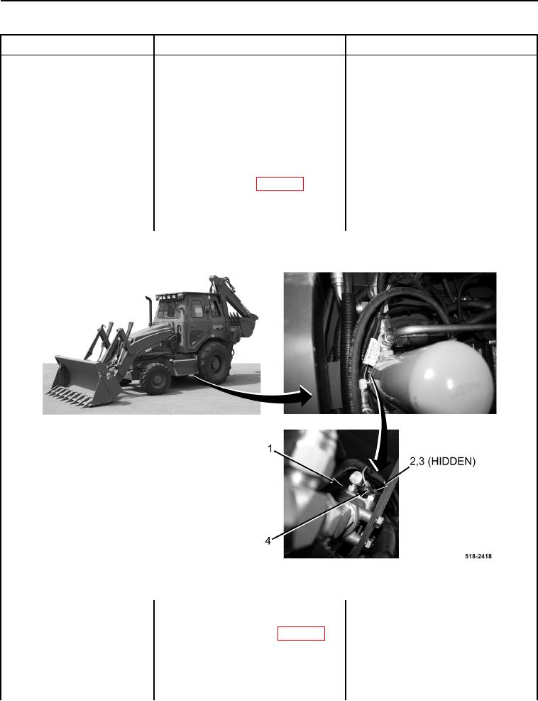
2. Remove nut (Figure 2, Item 2) and
washer (Figure 2, Item 3) and dis-
connect main chassis wiring har-
ness connector (WP 0007, Figure
39) eyelet (Figure 2, Item 4) from
hydraulic oil filter restriction switch
(Figure 2, Item 1).
Figure 2. Hydraulic Oil Filter Restriction Switch.
0027
3. Using a digital multimeter, test for
Continuity - Replace hydraulic oil filter
continuity between hydraulic oil fil-
head assembly (WP 0268).
ter restriction switch (WP 0007,
Proceed to Test Step 10.
Figure 39) and machine ground.
No Continuity - Proceed to Test Step 4.
There should be no continuity.