TM 5-2420-231-23-1
0030
Table 1. Heating and A/C Troubleshooting Procedures - Continued.
030
MALFUNCTION
TEST OR INSPECTION
CORRECTIVE ACTION
2. A/C Does Not Blow Cold
3. Remove blower ducts (Figure 25,
Air When A/C
Item 10) (WP 0350).
Temperature Control Is
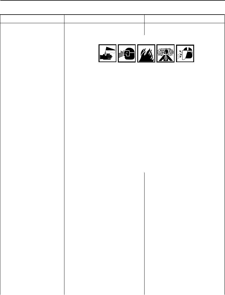
WARNING
Set to Maximum Cold -
Continued
Contact with refrigerant can cause frostbite. Keep hands and face away
to prevent personal injury.
Protective face shield and gloves must always be worn when refrigerant
lines are opened, even if the gauges indicate that the system is empty.
Always use caution when disconnecting fittings. Slowly loosen fittings in a
well-ventilated area.
Do not smoke when servicing A/C or wherever refrigerant gas may be
present.
Only service A/C system in a well-ventilated area.
Failure to follow these warnings may result in injury or death to
personnel.
CAUTION
Plug and cap all hoses and fittings to prevent contamination. Failure to
follow this caution may cause damage to machine.
NOTE
Tag and mark A/C lines to aid in installation.
4. Remove butyl tape (Figure 25,
Item 1) from expansion valve (Fig-
ure 25, Item 2) (WP 0361).
5. Remove two bolts (Figure 25, Item
5) and bracket (Figure 25, Item 6)
from machine.
6. Disconnect cab high-pressure A/C
tube (Figure 25, Item 3) and O-ring
(Figure 25, Item 4) from A/C
expansion valve (Figure 25, Item
2). Discard O-ring.
7. Plug and cap A/C expansion valve
(Figure 25, Item 2).
8. Remove cab floor cover plate (WP
0306).
9. Disconnect high-pressure A/C
hose (Figure 25, Item 7) and
O-ring (Figure 25, Item 8) from cab
high-pressure A/C tube (Figure 25,
Item 9) (WP 0361). Discard O-ring.
0030-33

