
TM 5-2420-231-23-1
0040
Table 1. Front and/or Rear Turn Signals Do Not Function Correctly - Continued.
040
MALFUNCTION
TEST OR INSPECTION
CORRECTIVE ACTION
NOTE
Front and/or Rear Turn
Signals Do Not Function
It may be necessary to manually select voltage range on digital
Correctly - Continued
multimeter.
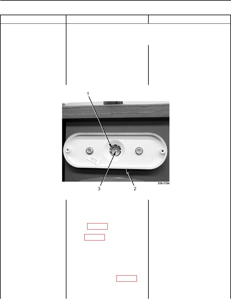
5. Using digital multimeter, place red
Voltage Pulses Between 0 and 14
lead on center contact (Figure 7,
Volts - Replace bulb (WP 0180).
Item 3) and black lead on shield
Proceed to Test Step 13.
(Figure 7, Item 1) of left front turn
No Voltage - Proceed to step 6.
signal light (Figure 7, Item 2). Volt-
age should pulse between 0 and
14 volts.
Figure 7. Turn Signal Light Socket.
0040
6. Turn ignition switch off (TM 5-
2420-231-10) and disconnect bat-
teries (WP 0157).
7. Disconnect rear left turn signal
light (WP 0007, Figure 93) from
rear lights wiring harness connec-
tor (WP 0007, Figure 92) (WP
0180).
8. Connect batteries (WP 0157) and
turn ignition switch to the on posi-
tion (TM 5-2420-231-10).
9. Using a digital multimeter, test for
Voltage Pulses Between 0 and 14
voltage between rear lights wiring
Volts - Replace rear left turn signal
harness connector (WP 0007, Fig-
lamp (WP 0180).
ure 92) terminals 1 and 2. Voltage
Proceed to Test Step 13.
should pulse between 0 and 14
No Voltage - Proceed to Test Step 5.
volts.