
TM 5-2420-231-23-1
0040
Table 1. Front and/or Rear Turn Signals Do Not Function Correctly - Continued.
040
MALFUNCTION
TEST OR INSPECTION
CORRECTIVE ACTION
Front and/or Rear Turn
Signals Do Not Function
Correctly - Continued
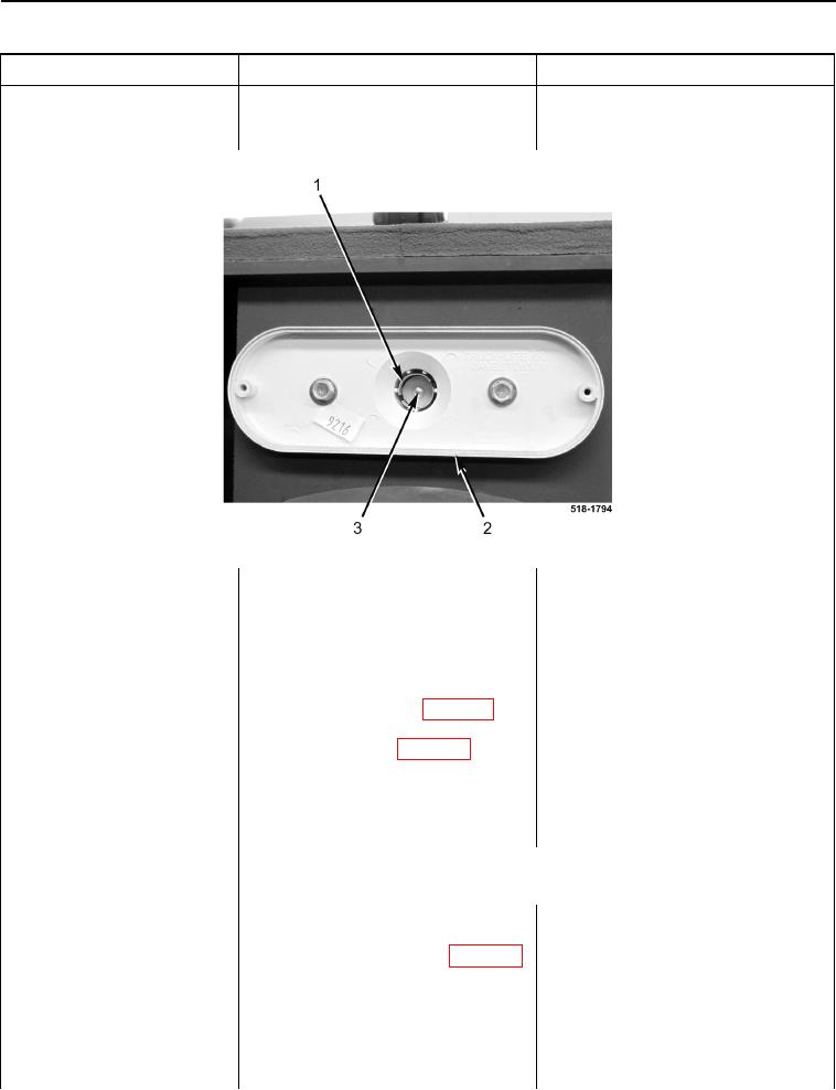
Figure 13. Turn Signal Light Socket.
0040
6. Turn ignition switch off (TM 5-
2420-231-10) and disconnect bat-
teries (WP 0157).
7. Remove rear floor cover plate
(WP 0306).
8. Disconnect main chassis wiring
harness connector (WP 0007, Fig-
ure 87) from rear lights wiring har-
ness connector (WP 0007, Figure
86).
9. Connect batteries (WP 0157) and
turn ignition switch to the on posi-
tion (TM 5-2420-231-10).
NOTE
Ensure right turn signal is in on position.
10. Using a digital multimeter, test for
Voltage Pulses Between 0 and 14
voltage between main chassis wir-
Volts - Replace rear lights wiring
ing harness connector (WP 0007,
harness (WP 0184).
Figure 87) terminal D and machine
Install bulb and lens (WP 0180).
ground. Voltage should pulse
Proceed to Test Step 13.
between 0 and 14 volts.
No Voltage - Replace main chassis
wiring harness (WP 0154).
Install bulb and lens (WP 0180).
Proceed to Test Step 13.