
TM 5-2420-231-23-1
0043
Table 1. Display and/or Backup Alarm Does Not Turn On - Continued.
043
MALFUNCTION
TEST OR INSPECTION
CORRECTIVE ACTION
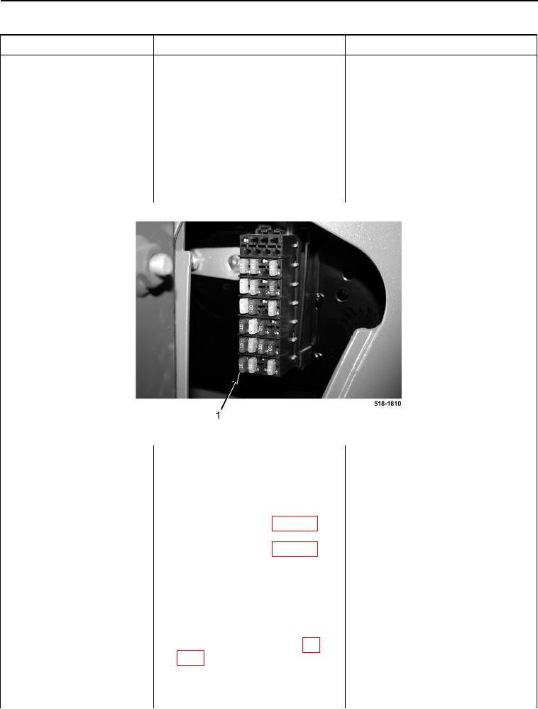
2. Remove starting transmission con-
Display and/or Backup
trol fuse (Figure 2, Item 1) (TM 5-
Alarm Does Not Turn On -
2420-231-10).
Continued
3. Using a digital multimeter, mea-
Resistance 5.0 Ohms or Less - Install
sure resistance between terminals
starting transmission control fuse (TM
of starting transmission control
5-2420-231-10).
fuse. Resistance should be 5.0
Proceed to Test Step 19.
ohms or less.
Resistance Greater Than 5.0 Ohms -
Replace starting transmission control
fuse (TM 5-2420-231-10).
Proceed to Test Step 21.
Figure 2. Fuse Panel.
0043
Test Step 19. Test for Power to
Powershift Wiring Harness.
1. Remove instrument panel front
cover (WP 0174).
2. Disconnect front console wiring
harness connector (WP 0007, Fig-
ure 112) from powershift wiring
harness connector (WP 0007, Fig-
ure 113).
3. Connect batteries (WP 0157) and
turn ignition switch to the on posi-
tion (TM 5-2420-231-10).
4. Using a digital multimeter, mea-
Voltage 10 to 14 Volts - Replace
sure voltage between front console
powershift wiring harness (WP 0167).
wiring harness connector (WP
Proceed to Test Step 30.
0007, Figure 112) terminal D and
Voltage Less Than 10 Volts - Proceed
machine ground. Voltage should
to Test Step 20.
be 10 to 14 volts.