
TM 5-2420-231-23-1
0062
Table 1. One Wheel Spins When Rear Differential Lock Switch Is Depressed - Continued.
062
MALFUNCTION
TEST OR INSPECTION
CORRECTIVE ACTION
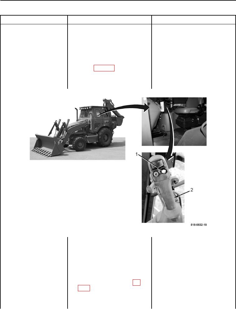
5. Press and hold differential lock
One Wheel Spins When Rear
switch (Figure 4, Item 1) on man-
Differential Lock Switch Is
ual control lever (Figure 4, Item 2)
Depressed - Continued
(TM 5-2420-231-10).
6. Using a digital multimeter, mea-
Resistance 5.0 Ohms or Less -
sure resistance between manual
Proceed to Test Step 4.
control handle wiring harness con-
Resistance Greater Than 5.0 Ohms -
nector (WP 0007, Figure 116) ter-
Install front floor cover plate (WP 0306).
minals C and D. Resistance should
Replace manual control handle (WP
be 5.0 ohms or less.
0277).
Proceed to Test Step 7.
Figure 4. Manual Control Lever and Differential Lock Switch.
0062
Test Step 4. Test Manual Control
Lever Switch Voltage Supply Circuit.
1. Connect batteries (WP 0157) and
turn ignition switch to the on posi-
tion (TM 5-2420-231-10).
2. Using a digital multimeter, mea-
Voltage 10 to 14 Volts - Proceed to
sure voltage between powershift
Test Step 5.
wiring harness connector (WP
Voltage Less Than 10 Volts - Install
0007, Figure 115) terminal D and
front floor cover plate (WP 0306).
machine ground. Voltage should
Replace powershift wiring harness (WP
be 10 to 14 volts.
0167).
Proceed to Test Step 7.