
TM 5-2420-231-23-2
0133
INSTALLATION CONTINUED
NOTE
Route drive belt as noted during removal.
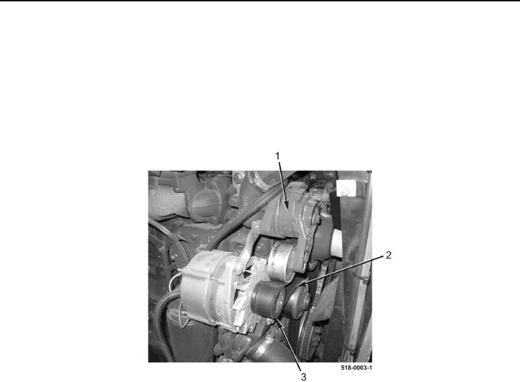
4. Rotate drive belt tensioner (Figure 5, Item 1) clockwise and install drive belt (Figure 5, Item 2) on alternator pul-
ley (Figure 5, Item 3) and drive belt tensioner (Figure 5, Item 1).
5. Release drive belt tensioner (Figure 5, Item 1).
Figure 5. Drive Belt.
0133
END OF TASK
FOLLOW-ON TASKS
0133
1. Lower engine hood (TM 5-2420-231-10).
2. Disengage and stow safety support strut, and lower front end loader (TM 5-2420-231-10).
END OF TASK
END OF WORK PACKAGE