
TM 5-2420-231-23-2
0141
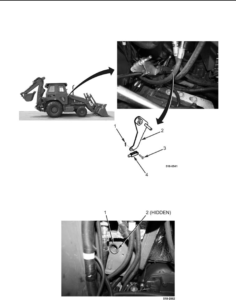
REMOVAL CONTINUED
6. Remove two cotter pins (Figure 4, Item 1), clevis pins (Figure 4, Item 3), and clevis (Figure 4, Item 4) from foot
throttle assembly (Figure 4, Item 2). Discard cotter pins.
7. Remove foot throttle assembly (Figure 4, Item 2) from machine.
Figure 4. Clevis Assembly.
0141
8. Remove bellows (Figure 5, Item 1) and retaining ring (Figure 5, Item 2) from machine.
Figure 5. Bellows.
0141