
TM 5-2420-231-23-2
0170
INSTALLATION
0170
1. Install side console wiring harness (Figure 8, Item 3) on machine.
NOTE
Install tiedown straps in quantity and locations as noted during removal.
2. Install tiedown straps (Figure 8, Item 6) on side console wiring harness (Figure 8, Item 3).
3. Connect side options wiring harness connector (Figure 8, Item 5) to side console wiring harness connector
(Figure 8, Item 4).
4. Connect cab wiring harness connector (Figure 8, Item 1) to side console wiring harness connector
(Figure 8, Item 2).
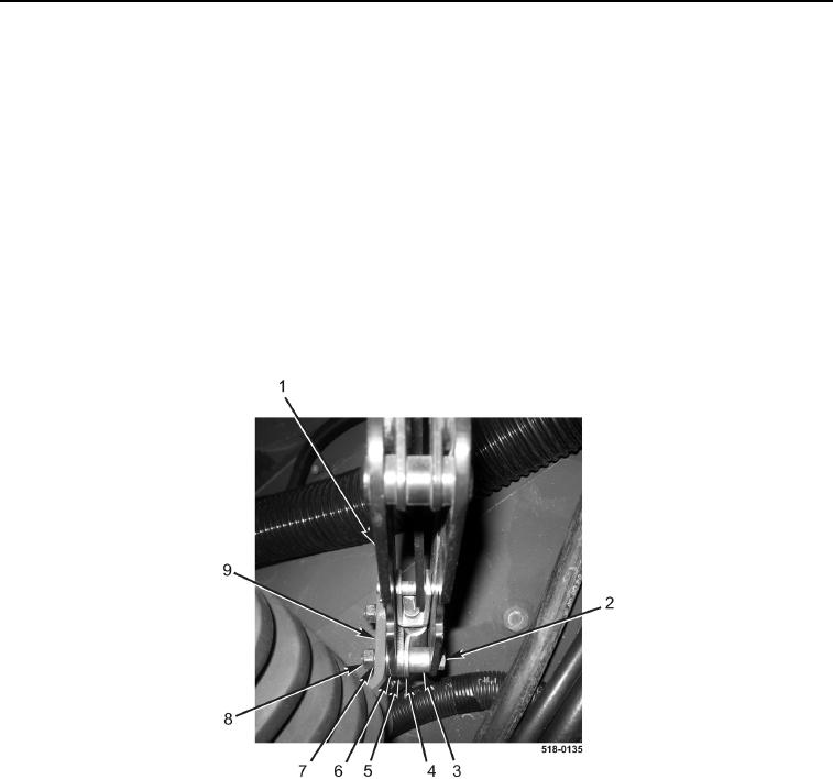
5. Install parking brake lever assembly (Figure 9, Item 1), spacer (Figure 9, Item 3), cable clamp (Figure 9,
Item 4), spacer (Figure 9, Item 5), two washers (Figure 9, Item 6), bolt (Figure 9, Item 2), new lockwashers
(Figure 9, Item 7), and nuts (Figure 9, Item 8) on bracket (Figure 9, Item 9).
Figure 9. Parking Brake Lever Assembly.
0170