
TM 5-2420-231-23-2
0177
INSTRUMENT PANEL REMOVAL CONTINUED
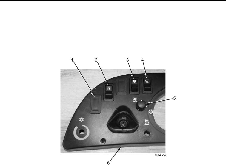
14. Remove two covers (Figure 11, Item 1) from instrument panel (Figure 11, Item 6).
15. Remove four-wheel-drive switch (Figure 11, Item 2) from instrument panel (Figure 11, Item 6).
16. Remove ride control switch (Figure 11, Item 3) from instrument panel (Figure 11, Item 6).
17. Remove light switch (Figure 11, Item 4) from instrument panel (Figure 11, Item 6).
18. Remove blower control knob (Figure 11, Item 5) from instrument panel (Figure 11, Item 6).
Figure 11. Instrument Panel Switches.
0177