
TM 5-2420-231-23-2
0179
CLEANING AND INSPECTION
0179
1. Clean and inspect all parts IAW Mechanical General Maintenance Instructions (WP 0369).
2. Clean and inspect all parts IAW Electrical General Maintenance Instructions (WP 0370).
END OF TASK
INSTALLATION
0179
NOTE
The procedure for front blackout marker light removal and replacement is identical for left-
hand and right-hand front blackout marker lights. Left-hand front blackout marker light is
shown in this procedure.
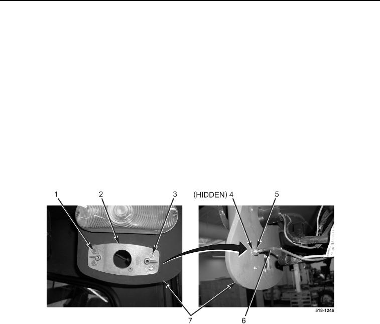
1. Install light base (Figure 6, Item 2) and three screws (Figure 6, Item 1) on light bracket (Figure 6, Item 7).
2. Install screw (Figure 5, Item 3), wire (Figure 5, Item 6), new lockwasher (Figure 5, Item 4), and new locknut
(Figure 5, Item 5) on light base (Figure 5, Item 2).
Figure 6. Light Base.
0179