
TM 5-2420-231-23-2
0213
INSTALLATION CONTINUED
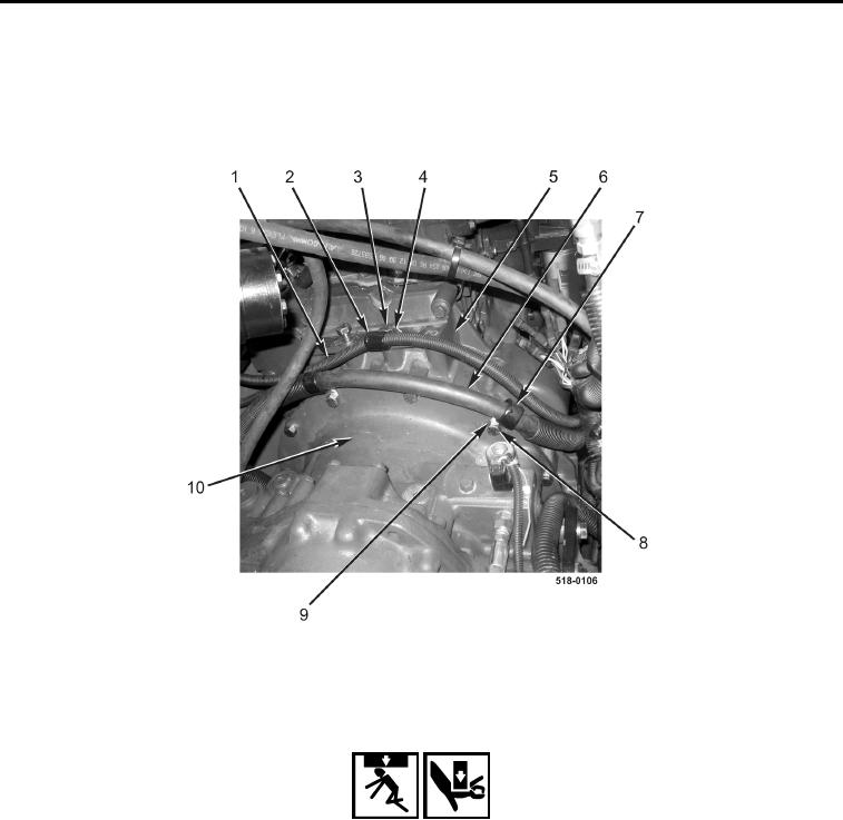
43. Position heater hose (Figure 46, Item 6) and install two clamps (Figure 46, Item 7), washers (Figure 46,
Item 9), and bolts (Figure 46, Item 8) on transmission bell housing (Figure 46, Item 10).
44. Position cold start B+ cable (Figure 46, Item 1) and install clamp (Figure 46, Item 2), washer (Figure 46,
Item 4), and bolt (Figure 46, Item 3) on engine (Figure 46, Item 5).
Figure 46. Heater Hose Clamps.
0213
45. Attach nylon sling to hydraulic pump (Figure 47, Item 3).
WARNING
Use extreme caution when handling heavy parts. Provide adequate support and use
assistance during procedure. Failure to follow this warning may result in injury or death to
personnel.
Install two top bolts first to avoid working underneath the pump while mounting. Failure to
follow this warning may result in injury or death to personnel.
NOTE
The hydraulic pump weighs 90 lb (41 kg).
46. With assistance, install hydraulic pump (Figure 47, Item 3), two washers (Figure 47, Item 1), and top bolts
(Figure 47, Item 2) on transmission.
47. Remove nylon sling from hydraulic pump (Figure 47, Item 3).