
TM 5-2420-231-23-3
0309
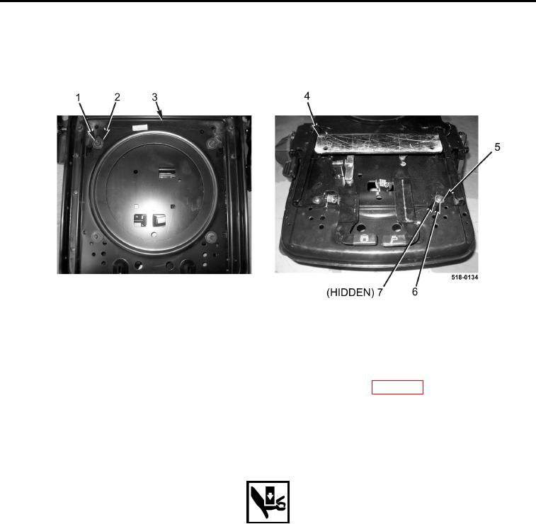
REMOVAL CONTINUED
8. Remove four locknuts (Figure 6, Item 1), washers (Figure 6, Item 2), seat (Figure 6, Item 3), four washers
(Figure 6, Item 7), washers (Figure 6, Item 5), and bolts (Figure 6, Item 6) from swivel (Figure 6, Item 4).
Discard locknuts.
Figure 6. Seat and Swivel Assembly.
0309
END OF TASK
CLEANING AND INSPECTION
0309
Clean and inspect all parts IAW Mechanical General Maintenance Instructions (WP 0369).
END OF TASK
INSTALLATION
0309
WARNING
Use extreme caution when sliding seat components. Keep hands and fingers away from
moving parts when sliding seat mechanism. Failure to follow this warning may result in
injury to personnel.
NOTE
It may be necessary to slide seat fore and aft to access hardware.
1. Install four bolts (Figure 6, Item 6), washers (Figure 6, Item 5), washers (Figure 6, Item 7), seat (Figure 6,
Item 3), four washers (Figure 6, Item 2), and new locknuts (Figure 6, Item 1) on swivel (Figure 6, Item 4).