
TM 5-2420-231-23-3
0341
INSTALLATION
0341
NOTE
Install wiper arm as noted during removal.
Align wiper blade to wiper arm as noted during removal.
1. Install sleeve (Figure 3, Item 3), wiper blade (Figure 3, Item 4), bolt (Figure 3, Item 5), and new locknut
(Figure 3, Item 2) on wiper arm (Figure 3, Item 1).
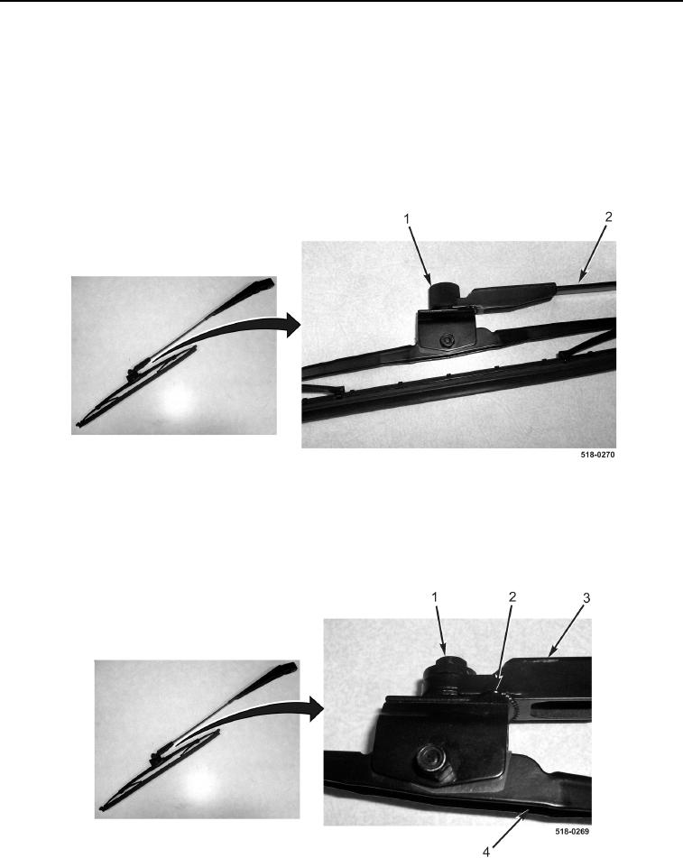
2. Remove bolt cover (Figure 4, Item 1) from wiper arm (Figure 4, Item 2).
Figure 4. Bolt Cover.
0341
3. Loosen nut (Figure 5, Item 1) on wiper arm (Figure 5, Item 3).
4. Align wiper blade (Figure 5, Item 4) to wiper arm locking teeth (Figure 5, Item 2).
5. Tighten nut (Figure 5, Item 1) on wiper arm (Figure 5, Item 3).
Figure 5. Adjustment Nut.
0341