
TM 5-3805-255-14
0003
ELECTRICAL SYSTEM CONTINUED
Regulator
0003
1. To prevent the alternator from producing too much voltage and burning out the accessories and overcharging
the battery, its voltage must be limited. For this function, a regulator is necessary in the charging system.
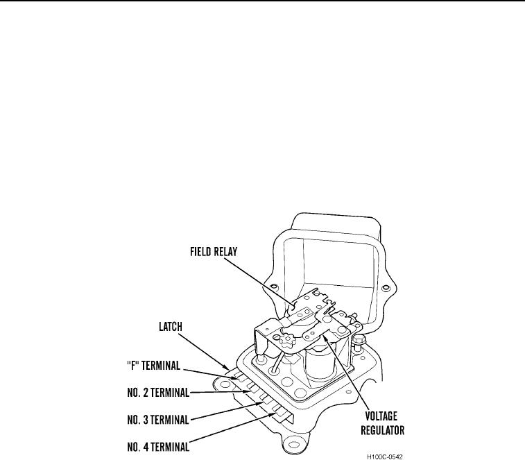
2. A typical double contact regulator is shown in Figure 5. This regulator has four terminals.
3. The terminals are of the slip-connection type, and a special connector body on the vehicle wiring harness is
keyed to mating slots in the regulator base to insure proper connections. Also, a projection on the connector
body serves to latch the assembly together. This prevents disconnection due to vibration. The assembly can be
disconnected by lifting the latch slightly.
4. A double contact voltage regulator unit and field relay unit make up the regulator assembly. The voltage
regulator unit operates to limit alternator voltage to a pre-set value, whereas the field relay connects alternator
field winding and regulator winding directly to the battery.
Figure 5. Typical Two-Unit Regulator.
03
0003-8