TM 5-3805-255-14
0003
ELECTRICAL SYSTEM CONTINUED
Regulator Continued
5. This model regulator is designed for use on only one polarity system. Note the marking on the regulator base,
or refer to specifications to determine if polarity of the regulator is negative or positive.
CAUTION
On electrical systems using these regulators, the polarity of the regulator, alternator, and
battery must be the same. When installing any one of these three units, do not make any
connections without first checking polarities. Failure to follow this caution may result in
damage to equipment.
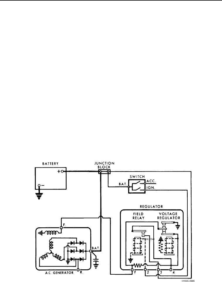
6. A typical wiring diagram showing internal circuits of the regulator is shown in Figure 6.
7. On some circuits, a condenser may be connected to the No. 4 regulator terminal. If a condenser is not used,
neither is the No. 4 terminal.
NOTE
Do not connect anything to the No. 4 terminal other than a condenser.
8. Following is a brief description of the operating principles of the units in this type of circuit. When the switch is
closed, the field relay winding in the regulator is connected directly to the battery. The magnetism created in
the winding attracts the relay armature toward the core, causing the contacts to close. This connects the
alternator field winding directly to the battery, allowing field current to flow from the battery to the regulator No.
3 terminal, through the field relay contacts and then through the voltage regulator lower or series contacts.
Current continues to flow to the regulator "F" terminal, and then through the alternator field winding to ground.
9. When the alternator begins to operate, AC voltages are generated in the stator windings, and these voltages
are then changed or rectified to a DC voltage which appears at the "BAT" or output terminal on the alternator.
Figure 6. Typical Wiring Diagram Showing Internal Circuits.
03
0003-9

