
TM 5-3805-255-14
0003
PROPELLER SHAFT/UNIVERSAL JOINTS
0003
General Information
0003
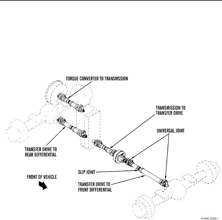
1. The purpose of the propeller shafts is to transmit power. All the propeller shafts on the loader are similar in
construction. There is a universal joint located at each end of the shaft to permit pivoting in all directions and
accommodate any misalignment. A slip joint is provided to allow the shaft to telescope, to compensate for
changes in the distance between the connected components.
2. During normal operation, the rear axle undergoes considerable axial movement due to surface irregularities
and varying axle loads. Each time these conditions are encountered, a proportional change in the overall
length of the propeller shaft occurs. The slip joint accommodates these variations by telescoping. This
eliminates the forces of tension that would be present in a shaft not so equipped.
Figure 11. Propeller Shafts.
03
0003-16