
TM 5-3805-255-14
0003
BRAKE SYSTEM CONTINUED
0003
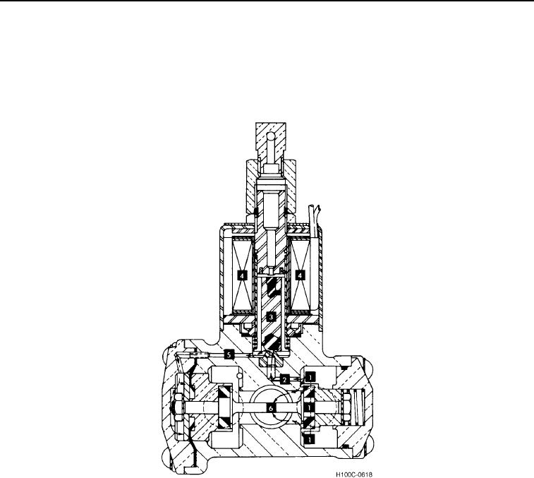
When the coil (Figure 19, Item 4) is energized, the plunger moves upward against the stop. The upward movement
allows the air flow from passageway (Figure 19, Item 2) into the passageway (Figure 19, Item 5) to the diaphragm.
The air pressure in the diaphragm cavity overcomes the spring force on the opposite end of the spindle. The spin-
dle movement allows the flow (Figure 19, Item 1) into the spindle cavity and through the outlet port (Figure 19, Item
6) to the transmission and brakes.
Figure 19. Cutaway of Air Solenoid Valve (Opened).
03
0003-25