
TM 5-3805-255-14
0003
FRAME CONTINUED
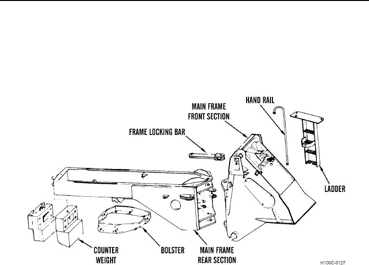
Each main frame component is composed of many smaller items welded together to form a single rigid assembly,
Bushings are pressed into bores at pivot points and the counterweight is bolted to the rear of the frame section.
The two frame sections are connected at their hinge points by a pin and bearing assembly. The rear axle bolster is
connected to the rear main frame by a pin and bushing arrangement.
The frame locking bar is pinned and locked to the side of the rear frame section in its rest position. The bar and
pins are used to lock the two tractor halves when the loader is serviced or transported.
Figure 22. Main Frame Assembly.
03
0003-28