
TM 5-3805-255-14
0003
FRAME CONTINUED
The instrument panel and box are mounted on the front main frame, to the left of the operator's seat. All wires
leading to the instrument panel pass through a common connector at the base of the instrument box.
The hydraulic control valve is fastened beneath the platform floor in the right rear corner of the enclosure.
Boom and Bucket
0003
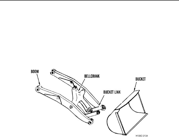
The loader linkage and bucket transform the energy produced by the loader hydraulics into a visible working force.
The hydraulic lift cylinders raise and lower the boom and the bucket cylinder actuates the bucket through the
bellcrank and bucket link. The bucket may be moved from the fully retracted to the fully dumped position in a few
seconds.
The boom is of welded steel construction. The bellcrank, joining the boom arms at its pivot point, is a one piece
casting.
Figure 25. Boom and Bucket (4.5 cu. Yard Bucket Shown).
03
0003-31