
TM 5-3805-255-14
0020
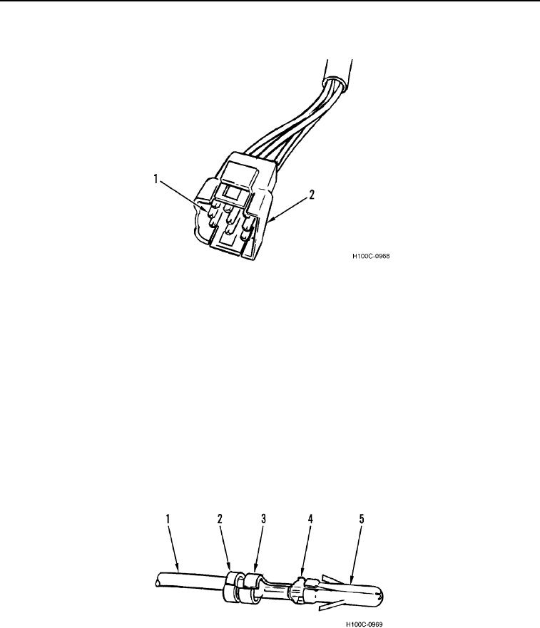
CONNECTOR REPAIR CONTINUED
Figure 2. Connector Repair.
0020
2. Remove wire (Figure 3, Item 1), with pin (Figure 3, Item 5) attached, from rear of connector.
3. If defective, remove pin (Figure 3, Item 5) from wire (Figure 3, Item 1) by cutting through wire just behind pin.
4. Using wire stripping tool, strip insulation off wire (Figure 3, Item 1) to expose proper length of metal strands
(Figure 3, Item 4).
5. Using crimping tool, securely crimp tabs (Figure 3, Item 3) of pin (Figure 3, Item 5) over metal strands (Figure
3, Item 4) of wire (Figure 3, Item 1).
NOTE
The other two tabs of pin may need to be crimped slightly in order to enter connector.
6. Using crimping tool, crimp tabs (Figure 3, Item 2) at rear of pin (Figure 3, Item 5) over insulation of wire (Figure
3, Item 1).
Figure 3. Connector Repair
0020
7. Push pin (Figure 2, Item 1) into rear of connector (Figure 2, Item 2) until fully seated.
0020-3