
TM 5-3805-255-14
0020
WATERPROOF CONNECTOR REPAIR
00020
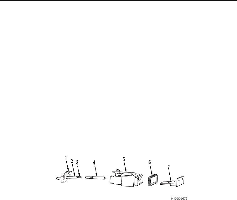
1. Remove end cover (Figure 6, Item 7) and gasket (Figure 6, Item 6) from front of connector (Figure 6, Item 5).
2. Remove seal (Figure 6, Item 1) from rear of connector (Figure 6, Item 5) and slide seal back on wire (Figure 6,
Item 2).
NOTE
Perform steps 3 through 9 for each wire of connector.
Tag wires for installation.
3. Using pin removal tool, insert tool into front of connector (Figure 6, Item 5) and depress locking tab of connec-
tor.
4. Remove wire (Figure 6, Item 2) with pin (Figure 6, Item 4) from rear of connector (Figure 6, Item 5).
5. If defective, remove pin (Figure 6, Item 4) from wire (Figure 6, Item 2) by cutting through wire just behind pin.
6. Using wire stripping tool, strip insulation off wire (Figure 6, Item 2) to expose 1/4 in. (6 mm) length of metal
strands (Figure 6, Item 3).
7. Insert metal strands (Figure 6, Item 3) of wire (Figure 6, Item 2) fully into rear of pin (Figure 6, Item 4).
8. Using crimping tool, securely crimp pin (Figure 6, Item 4) to metal strands (Figure 6, Item 3) of wire (Figure 6,
Item 2).
9. Push pin (Figure 6, Item 4) into rear of connector (Figure 6, Item 5) until fully seated.
10. Install seal (Figure 6, Item 1) on rear of connector (Figure 6, Item 5).
11. Install gasket (Figure 6, Item 6) and end cover (Figure 6, Item 7) on front of connector (Figure 6, Item 5).
Figure 6. Waterproof Connector Repair.
0020
0020-6