
TM 5-3805-255-14
0030
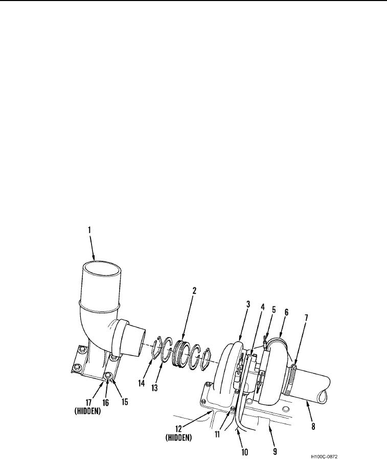
REMOVAL
00030
1. Disconnect oil inlet tube (Figure 1, Item 4) from turbocharger (Figure 1, Item 3).
2. Disconnect oil drain tube (Figure 1, Item 10) from turbocharger (Figure 1, Item 3).
3. Loosen clamp (Figure 1, Item 5) from air discharge hose (Figure 1, Item 6).
4. Remove clamp (Figure 1, Item 7) from air inlet hose (Figure 1, Item 8).
NOTE
Exhaust sleeve is loosely held between exhaust elbow and turbocharger. Sleeve must be
held as turbocharger is removed, to prevent sleeve from dropping.
5. Remove four bolts (Figure 1, Item 16), two nuts (Figure 1, Item 17), and four washers (Figure 1, Item 15) from
exhaust manifold (Figure 1, Item 9).
6. Remove exhaust elbow (Figure 1, Item 1) from exhaust manifold (Figure 1, Item 9) and from turbocharger
(Figure 1, Item 3).
7. Remove four nuts (Figure 1, Item 11) from exhaust manifold (Figure 1, Item 9).
8. Remove turbocharger (Figure 1, Item 3) and gasket (Figure 1, Item 12) from exhaust manifold (Figure 1,
Item 9). Discard gasket.
9. Remove exhaust sleeve (Figure 1, Item 2), seal (Figure 1, Item 14), and seal ring (Figure 1, Item 13) from
exhaust elbow (Figure 1, Item 1).
Figure 1. Turbocharger.
030
END OF TASK
0030-2