
TM 5-3805-255-14
0064
ASSEMBLY CONTINUED
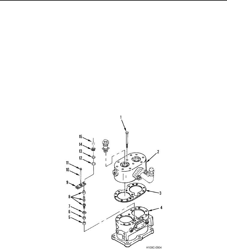
24. Install ring (Figure 20, Item 7), bushing (Figure 20, Item 5), and grommet (Figure 20, Item 6) on cylinder block
(Figure 20, Item 4).
25. Install unloader pistons (Figure 20, Item 8) in cylinder block (Figure 20, Item 4).
26. Install spring saddle (Figure 20, Item 9), unloader spring (Figure 20, Item 10), and unloader seat (Figure 20,
Item 11) on cylinder block (Figure 20, Item 4).
NOTE
The dimension from top of the cylinder block to the inlet valve seat should not exceed
0.118 in. (2.99 mm) or be less than 0.101 in. (2.56 mm). If inlet valves cannot be reclaimed
by lapping with crocus cloth, replace inlet valves.
27. Install two inlet valve seats (Figure 20, Item 12), valve guides (Figure 20, Item 14), inlet valves (Figure 20,
Item 13), and valve springs (Figure 20, Item 15) on cylinder block (Figure 20, Item 4).
28. Align cylinder head inlet valve springs (Figure 20, Item 15) with inlet valve guides (Figure 20, Item 14) in
cylinder block (Figure 20, Item 4). Install new cylinder head gasket (Figure 20, Item 3), cylinder head
(Figure 20, Item 2), and ten bolts (Figure 20, Item 1) on cylinder block.
Figure 20. Air Compressor.
0064
0064-21