
TM 5-3805-255-14
0065
ASSEMBLY
00065
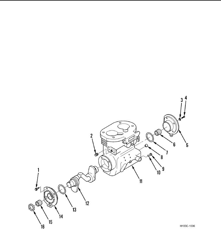
1. Install new gasket (Figure 7, Item 10) and plug (Figure 7, Item 9) on crankcase (Figure 7, Item 11).
2. Install plug (Figure 7, Item 2) on crankcase (Figure 7, Item 11).
3. Install plug (Figure 7, Item 8) on crankcase (Figure 7, Item 11).
4. Press ball bearings (Figure 7, Items 6 and 15) on crankshaft (Figure 7, Item 12).
5. Press crankshaft (Figure 7, Item 12) with ball bearings (Figure 7, Items 6 and 15) in crankcase (Figure 7, Item
11) from drive end of compressor.
6. Install new gasket (Figure 7, Item 7) on rear cover (Figure 7, Item 5).
7. Install four new lockwashers (Figure 7, Item 3), bolts (Figure 7, Item 4), and rear cover (Figure 7, Item 5) on
crankcase (Figure 7, Item 11).
8. Install new gasket (Figure 7, Item 13) and oil seal ring (Figure 7, Item 16) on front cover (Figure 7, Item 14).
9. Install front cover (Figure 7, Item 14) and four bolts (Figure 7, Item 1) on crankcase (Figure 7, Item 11).
Figure 7. Crankshaft.
0065
0065-9