
TM 5-3805-255-14
0065
INSTALLATION
00065
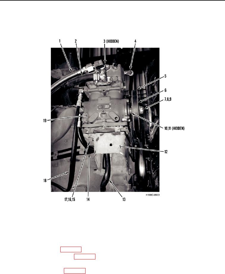
1. Install woodruff key (Figure 11, Item 11) on crankshaft (Figure 11, Item 10).
2. Install pulley (Figure 11, Item 6), washer (Figure 11, Item 9), and nut (Figure 11, Item 8) on crankshaft (Figure
11, Item 10). Install new cotter pin (Figure 11, Item 7).
Figure 11. Air Compressor Mounting.
0065
3. Install compressor (Figure 11, Item 19), four washers (Figure 11, Item 17), new lockwashers (Figure 11, Item
16), and nuts (Figure 11, Item 15) on mounting plate (Figure 11, Item 12). Do not tighten nuts.
4. Connect seven hoses (Figure 11, Items 1, 2, 3, 4, 13, 14, and 18) on compressor (Figure 11, Item 19).
5. Install compressor belt (Figure 11, Item 5) on pulley (Figure 11, Item 6) and adjust belt tension. Tighten four
nuts (Figure 11, Item 15).
6. Fill system with antifreeze (WP 0005).
7. Close drain valve on air reservoir (WP 0005).
8. Start engine and check air pressure. Check for oil or coolant leaks.
9. Install engine access panels (WP 0005).
END OF TASK
END OF WORK PACKAGE
0065-15/(16 blank)