
2
TM 5-3805-255-14
FIELD MAINTENANCE
-
WHEEL REPLACEMENT
0066
Removal, Installation
INITIAL SETUP
Tools and Special Tools
Equipment Condition
0
0
Tool Kit, General Mechanic's, Automotive (WP
Machine parked on level ground (WP 0005)
0
0128, Item 20)
Parking brake applied (WP 0005)
0
0
Engine OFF (WP 0005)
Materials/Parts
0
0
Battery disconnect switch in OFF position
Rag, Wiping (WP 0130, Item 28)
0
0
References
0
0
REMOVAL
00066
WARNING
Use extreme caution when handling heavy parts. Provide adequate support and use
assistance during procedure. Ensure that any lifting equipment used is in good condition
and of suitable load capacity. Keep clear of heavy parts supported by lifting equipment.
Failure to follow this warning may result in death or injury to personnel.
1. Using a suitable lifting device, lift loader until tire clears ground. Install suitable support under loader.
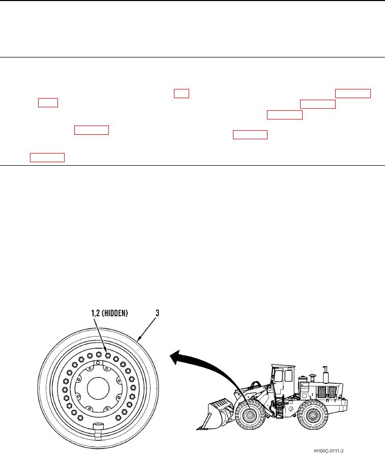
2. Install suitable lifting device on wheel (Figure 1, Item 3).
3. Remove 21 nuts (Figure 1, Item 1), washers (Figure 1, Item 2), and wheel (Figure 1, Item 3) from loader. Place
wheel on ground in a properly supported position. Remove lifting device from wheel.
Figure 1. Wheel Assembly.
066
END OF TASK
0066-1