
TM 5-3805-255-14
0111
DISASSEMBLY CONTINUED
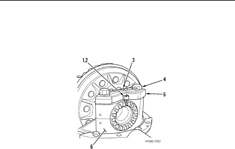
3. Mark two bearing caps (Figure 2, Item 5) and carrier housing legs (Figure 2, Item 6).
4. Remove two cotter pins (Figure 2, Item 1) and adjuster locks (Figure 2, Item 2) from bearing caps (Figure 2,
Item 5). Discard cotter pins.
5. Remove lockwire (Figure 2, Item 3) from bearing cap bolts (Figure 2, Item 4). Discard lockwire.
6. Remove four bearing cap bolts (Figure 2, Item 4) from two bearing caps (Figure 2, Item 5).
Figure 2. Marking Bearing Caps.
0111
0111-3