
TM 5-3805-255-14
0111
DISASSEMBLY CONTINUED
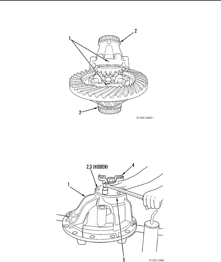
24. Remove two differential bearings (Figure 10, Item 2) from case half and case flange (Figure 10, Item 1).
Figure 10. Differential Bearings Removal.
0111
25. Rotate differential carrier (Figure 11, Item 1) in repair stand until assembled pinion (Figure 11, Item 4) faces up.
26. Remove six pinion bolts (Figure 11, Item 2), lockwashers (Figure 11, Item 3), and pinion bearing cap assembly
(Figure 11, Item 5) from carrier (Figure 11, Item 1). Discard lockwashers.
Figure 11. Pinion Bearing Cage Retainer Removal.
0111
0111-8