
TM 5-3805-255-14
0111
DISASSEMBLY CONTINUED
WARNING
Companion flange is heavy. Prevent dropping when removing from differential carrier.
Failure to follow this warning may result in personal injury and/or damage to the
components.
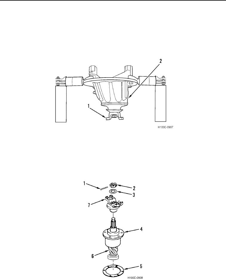
27. Remove assembled pinion (Figure 12, Item 1) from differential carrier (Figure 12, Item 2).
Figure 12. Pinion Removal.
0111
28. Remove shim or shims (Figure 13, Item 5) from assembled pinion (Figure 13, Item 4).
29. Wire shim pack together in order of removal and attach it to pinion (Figure 13, Item 4) for reference.
30. Secure yoke (Figure 13, Item 7) and remove cotter pin (Figure 13, Item 1), nut (Figure 13, Item 2), washer (Fig-
ure 13, Item 3), and pinion shaft (Figure 13, Item 6) from yoke (Figure 13, Item 7).
Figure 13. Pinion Disassembly.
0111
0111-9