
TM 5-3805-255-14
0121
DISASSEMBLY CONTINUED
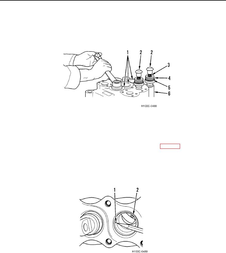
35. Remove three check valves (Figure 15, Item 1) from main valve body (Figure 15, Item 6).
36. Remove three check valve plugs (Figure 15, Item 4), springs (Figure 15, Item 3), and poppets (Figure 15, Item
2) from main valve body (Figure 15, Item 6).
37. Remove and discard three O-rings (Figure 15, Item 5) from poppets (Figure 15, Item 2).
Figure 15. Check Valves Removal.
0121
END OF TASK
CLEANING AND INSPECTION
000121
1. Thoroughly wash and inspect all parts IAW General Maintenance Instructions (WP 0019) in a clean mineral oil
solvent. Dry with filtered compressed air and place on clean paper for inspection.
2. Inspect all surfaces for burrs, scratches, nicks, scores, and other abrasions. Stone or lap all burrs. If scoring is
deep enough to produce excessive leakage, replace valve assembly. Stone or use crocus cloth on small
scores.
3. Check orifice (Figure 16, Item 1) in boom spool bore (Figure 16, Item 2) to be sure there are no obstructions.
Figure 16. Boom Spool Bore Inspection.
0121
0121-12