
TM 5-3805-255-14
0121
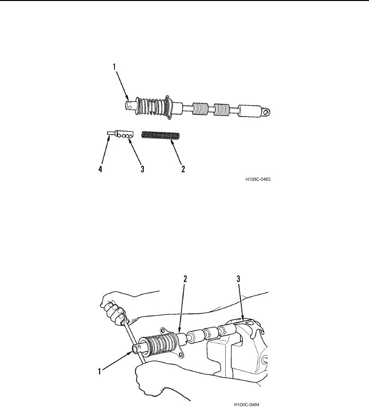
DISASSEMBLY CONTINUED
20. Slide spring (Figure 10, Item 2), detent cam (Figure 10, Item 4), and detent balls (Figure 10, Item 3) from
plunger assembly (Figure 10, Item 1).
Figure 10. Spring, Cam and Detent Balls Removal.
0121
CAUTION
Use caution to prevent damage to holes. Failure to follow this caution may result in
damage to components.
21. Place eye end of plunger (Figure 11, Item 3) in vise with protective jaws. Remove plunger pin (Figure 11, Item
1) from plunger assembly (Figure 11, Item 2) using a rod of approximate diameter of holes in end of plunger.
Figure 11. Plunger Removal.
0121
0121-7