Engine Tune-Up
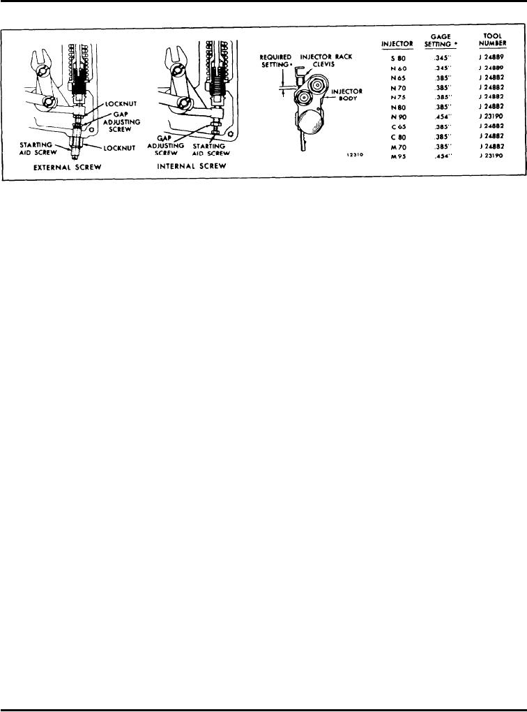
Fig. 6 - Starting Aid Screw Adjustment
IMPORTANT: The effectiveness of the starting
C A U T I O N : Once the No. IL and No. IR
aid screw will be eliminated if the speed control
injector rack control levers are adjusted, do not
lever is advanced to wide open throttle during
try to alter their settings. All adjustments are
starting.
made on the remaining control racks.
After the normal governor running gap of .0015" has
NOTE: Overtightening of the injector rack
been set and the injector racks positioned, adjust the
control lever adjusting screws during installa-
starting aid screw.
tion or adjustment can result in damage to the
injector control tube. The recommended torque
of the adjusting screws is 24-36 in-lb(3-4 Nm).
1 . On current turbocharged engines, adjust the
external starting aid screw as follows:
12. When all of the injector rack control levers are
adjusted, recheck their settings. With the control tube
a. With the engine stopped, place the governor stop
lever in the full-fuel position, check each control rack
lever in the run position and the speed control
as in Step 7. All of the control racks must have the
lever in the idle speed position.
same "spring" condition with the control tube lever in
the full-fuel position.
b. Adjust the starting a i d screw to obtain the
required setting between the shoulder on the
13. Insert the clevis pin in the fuel rod and the injector
injector rack clevis and the injector body (Fig. 6).
control tube levers.
Select the proper gage and measure the setting at
any convenient cylinder. When the starting aid
screw is properly adjusted, the gage should have a
14. Turn the idle speed adjusting screw in until it
small clearance of 1/64" (.397 mm) in the space
projects 3/16" from the lock nut, to permit starting
along the injector rack shaft between the rack
the engine.
clevis and the injector body.
15. Use new gaskets and replace the valve rocker
c. After completing the adjustment, hold the starting
covers.
aid screw and tighten the lock nut.
d. Check the injector rack clevis-to-body clearance
Adjust Starting Aid Screw - Turbocharged
after performing the following:
Engines
1. Position the stop lever in the run position.
The starting aid screw (Fig. 6) is threaded into the
governor housing of current engines and into the
2. Move the speed control lever from the idle
governor gap adjusting screw of early engines. This
speed position to the maximum speed position.
screw is adjusted to position the injector racks at less
than full fuel when the governor speed control lever is
3. Return the speed control lever to the idle speed
in the idle position. The reduced fuel makes starting
position.
easier and reduces the amount of smoke on start-up.
Page 95

