Engine Tune-Up
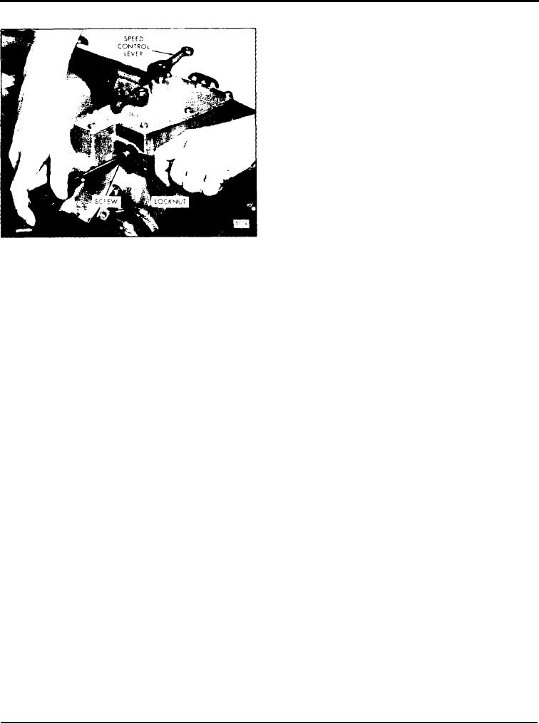
temperature and with the buffer screw backed out to
avoid contact with the differential lever, turn the idle
speed adjusting screw until the engine is operating at
approximately 15 rpm below the recommended idle
speed (Fig. 9). The recommended idle speed is 400-
450 rpm, but may vary with special engine
applications.
IMPORTANT: It may be necessary to use the
buffer screw to eliminate engine roll. Back out
the buffer screw, after the idle speed is
established, to the previous setting (5/8").
2. Hold the idle screw and tighten the lock nut.
3. Install the high-speed spring retainer cover and
tighten the two bolts.
Adjust Buffer Screw
Fig. 10 - Adjusting Buffer Screw
With the idle speed properly set, adjust the buffer
lever in the maximum speed position. Turn the high-
screw as follows:
speed spring retainer until the engine is operating at
the recommended no load speed.
1 . With the engine running at normal operating
temperature, turn the buffer screw (Fig. 10) in so that
3. Hold the high speed spring retainer and tighten the
it contacts the differential lever as lightly as possible
and still eliminates engine roll.
lock nut.
NOTE: Do not increase the engine idle speed
more than 15 rpm with the buffer screw.
Adjust Idle Speed
2. Recheck the maximum no-load speed. If it has
With the maximum no load speed properly adjusted,
increased more than 25 rpm, back off the buffer screw
adjust the idle speed as follows:
until the increase is less than 25 rpm.
I. With the engine running. at normal operating
3. Hold the buffer screw and tighten the lock nut.
LIMITING SPEED MECHANICAL GOVERNOR AND INJECTOR RACK
CONTROL ADJUSTMENT
16V-71 ENGINE
The governor (Fig. 1) on the 16V engine is mounted
injector control linkage has been disturbed, the control
on and driven from the front end of the rear blower.
link levers in the governor housing and auxiliary
control link housing must be aligned before proceed-
ing with the engine tune up. Refer to Fig. 2 and
After adjusting the exhaust valves and timing the fuel
position the control link levers as follows:
injectors. adjust the governor and Injector rack control
levers.
1. Disconnect the linkage to the governor speed control
lever and stop lever.
NOTE: Before proceeding with the governor and
injector r a c k adjustments. disconnect any
2. Remove the covers from the governor housing and
supplementary governing device. After the
auxiliary control link housing.
a d j u s t m e n t s are completed, reconnet and
adjust the supplementary governing device.
3. Disconnect the adjustable link from the lever in the
auxiliary control link housing.
If the engine or governor has been overhauled, or the
Page 98

