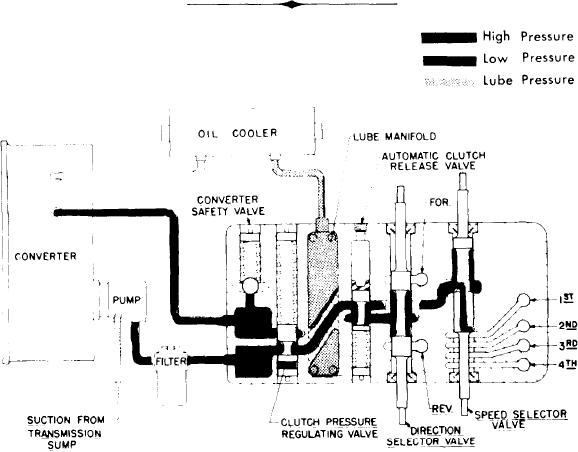
The direction or speed clutch assembly consists of a drum with internal gear teeth and a bore to receive a
hydraulically actuated piston. A piston is inserted into the bore of the drum. The piston is "oil tight" by the use
of sealing rings. A friction disc with internal teeth is inserted into the drum and rests against the piston. Next, a
disc with splines at the outer diameter is inserted. Discs are alternated until the required total is achieved. After
inserting the last disc, a series of springs and pins are assembled in such a manner that these springs rest on teeth
of the piston. A heavy back-up plate is then inserted and secured by a snap ring. A hub with I.D. and O.D. splines
is inserted into the splines of discs with teeth on the inner diameter and a splined shaft extending through the
clutch support. This hub is retained by a snap ring. The discs and inner shaft are free to increase in speed or
rotated in the opposite direction as long as no pressure is present in the direction or speed clutch.
To engage the clutch, as previously stated, the control valve is placed in the desired position. This allows oil
under pressure to flow from the control cover valve, through a tube in the transmission case, to a chosen clutch.
Once into the drum, oil is directed through a drilled hole into the rear side of the piston bore. Pressure of the
oil forces the piston and discs over against the heavy back-up plate. The discs, with teeth on the outer diameter,
clamping against discs, with teeth on inner diameter, enables the clutch drum and drive shaft to be locked to-
gether and allows them to turn as a unit.
There are bleed balls in the clutch drums which allow quick escape for oil when the pressure to the piston
is released.
The transmission gear train consists of six shafts: (1) Input Shaft, (2) Reverse Shaft, (3) Idler Shaft, (4) First
and Third Shaft, (5) Second and Fourth Shaft, (6) Output Shaft.
A screen mounted in a frame is positioned on the bottom of the transmission case, to screen out any foreign
material. This screen is covered by the sump pan. This pan is provided with magnets to catch any metallic particles.
Some transmissions may have an axle declutching unit as optional equipment, this unit consists of a split
output shaft with a sliding splined sleeve to engage or disengage the axle. This is accomplished by manually
shifting a lever in the operator's compartment which is mechanically connected to the shift fork on the clutch-
ing unit sliding sleeve. This unit, of course, is only used on the four wheel drive machine. On the front drive
only or the rear wheel drive only, the output shaft is a one piece type and an output flange assembled only
on the required end.
TRANSMISSION CONTROL COVER INTERNAL OILFLOW
-5-

